High Quality, Discrete Components Models, Input and Tone Control Modules
To complement the 60 Watt MosFet Audio Amplifier a High Quality Preamplifier design was necessary. A discrete components topology, using + and - 24V supply rails was chosen, keeping the transistor count to the minimum, but still allowing low noise, very low distortion and high input overload margin. Obviously, the modules forming this preamplifier can be used in different combinations and drive different power amplifiers, provided the following stages present a reasonably high input impedance (i.e. higher than 10KOhm).
Main Module:
If a Tone Control facility is not needed, the Preamplifier will be formed by the Main Module only. Its input will be connected to some sort of changeover switch, in order to allow several audio reproduction devices to be connected, e.g. CD player, Tuner, Tape Recorder, iPod, MiniDisc etc. The total amount and type of inputs is left to the choice of the home constructor. The output of the Main Module will be connected to a 22K Log. potentiometer (dual gang if a stereo preamp was planned). The central and ground leads of this potentiometer must be connected to the power amplifier input.
Circuit diagram: Main Module Circuit Diagram
Parts:
R1_____________1K5 1/4W Resistor
R2_____________220K 1/4W Resistor
R3_____________18K 1/4W Resistor
R4_____________330R 1/4W Resistor
R5_____________39K 1/4W Resistor
R6_____________56R 1/4W Resistor
R7,R10_________10K 1/4W Resistors
R8_____________33K 1/4W Resistor
R9_____________150R 1/4W Resistor
R11____________ 6K8 1/4W Resistor
R12,R13________100R 1/4W Resistors
R14____________100K 1/4W Resistor
C1_____________220nF 63V Polyester Capacitor
C2_____________220pF 63V Polystyrene or ceramic Capacitor
C3_____________1nF 63V Polyester or ceramic Capacitor
C4,C7__________47µF 50V Electrolytic Capacitors
C5,C6__________100µF 50V Electrolytic Capacitors
Q1,Q2__________BC550C 45V 100mA Low noise High gain NPN Transistors
Q3_____________BC556 65V 100mA PNP Transistor
Q4_____________BC546 65V 100mA NPN Transistor
R1_____________1K5 1/4W Resistor
R2_____________220K 1/4W Resistor
R3_____________18K 1/4W Resistor
R4_____________330R 1/4W Resistor
R5_____________39K 1/4W Resistor
R6_____________56R 1/4W Resistor
R7,R10_________10K 1/4W Resistors
R8_____________33K 1/4W Resistor
R9_____________150R 1/4W Resistor
R11____________ 6K8 1/4W Resistor
R12,R13________100R 1/4W Resistors
R14____________100K 1/4W Resistor
C1_____________220nF 63V Polyester Capacitor
C2_____________220pF 63V Polystyrene or ceramic Capacitor
C3_____________1nF 63V Polyester or ceramic Capacitor
C4,C7__________47µF 50V Electrolytic Capacitors
C5,C6__________100µF 50V Electrolytic Capacitors
Q1,Q2__________BC550C 45V 100mA Low noise High gain NPN Transistors
Q3_____________BC556 65V 100mA PNP Transistor
Q4_____________BC546 65V 100mA NPN Transistor
Tone Control Module:
This Module employs an unusual topology, still maintaining the basic op-amp circuitry of the Main Module with a few changes in resistor values. A special feature of this circuit is the use of six ways switches instead of the more common potentiometers: in this way, precise "tone flat" setting, or preset dB steps in bass and treble boost or cut can be obtained. Tone Control switches also allow a more precise channel matching when a stereo configuration is used, avoiding the frequent poor alignment accuracy presented by common ganged potentiometers. Six ways (two poles for stereo) rotary switches were chosen for this purpose as easily available. This dictated the unusual "asymmetrical" configuration of three positions for boost, one for flat and two for cut.
This choice was based on the fact that tone controls are used in practice more for frequency boosting than for cutting purposes. In any case, +5dB +10dB and +15dB of bass boost and -3dB and -10dB of bass cut were provided. Treble boost was also set to +5dB +10dB and +15dB and treble cut to -3.5dB and -9dB. Those wishing to use common potentiometers in the usual way for Tone Controls may use the circuit shown enclosed in the dashed box (bottom-right of the Tone Control Module circuit diagram) to replace switched controls. The Tone Control Module should usually be placed after the Main Input Module, and the volume control inserted between the Tone Control Module output and the power amplifier input. Alternatively, the volume control can also be placed between Main Input Module and Tone Control Module, at will. Furthermore, the position of these two modules can be also interchanged.
Circuit diagram:

Tone Control Module Circuit Diagram
Parts:
R1,R7___________47K 1/4W Resistors
R2_____________220K 1/4W Resistor
R3______________18K 1/4W Resistor
R4_____________330R 1/4W Resistor
R5______________39K 1/4W Resistor
R6______________56R 1/4W Resistor
R8_____________150R 1/4W Resistor
R9______________10K 1/4W Resistor
R10,R16__________6K8 1/4W Resistors
R11,R12________100R 1/4W Resistors
R13____________100K 1/4W Resistor
R14______________1K5 1/4W Resistor
R15,R21,R22______4K7 1/4W Resistors
R17,R24,R26______8K2 1/4W Resistors
R18______________3K3 1/4W Resistor
R19______________1K 1/4W Resistor
R20____________470R 1/4W Resistor
R23,R25_________12K 1/4W Resistors
R27,R28__________4K7 1/4W Resistors
C1_____________220nF 63V Polyester Capacitor
C2_______________1nF 63V Polyester or ceramic Capacitor
C3,C6___________47µF 50V Electrolytic Capacitors
C4,C5__________100µF 50V Electrolytic Capacitors
C7______________10nF 63V Polyester Capacitor
C8,C9__________100nF 63V Polyester Capacitors
Q1,Q2_________BC550C 45V 100mA Low noise High gain NPN Transistors
Q3____________BC556 65V 100mA PNP Transistor
Q4____________BC546 65V 100mA NPN Transistor
SW1,SW2_______2 poles 6 ways Rotary Switches
Simpler, alternative Tone Control parts:
P1______________22K Linear Potentiometer
P2______________47K Linear Potentiometer
R29,R30________470R 1/4W Resistors
R31,R32__________4K7 1/4W Resistors
C10_____________10nF 63V Polyester Capacitor
C11,C12________100nF 63V Polyester Capacitors
R2_____________220K 1/4W Resistor
R3______________18K 1/4W Resistor
R4_____________330R 1/4W Resistor
R5______________39K 1/4W Resistor
R6______________56R 1/4W Resistor
R8_____________150R 1/4W Resistor
R9______________10K 1/4W Resistor
R10,R16__________6K8 1/4W Resistors
R11,R12________100R 1/4W Resistors
R13____________100K 1/4W Resistor
R14______________1K5 1/4W Resistor
R15,R21,R22______4K7 1/4W Resistors
R17,R24,R26______8K2 1/4W Resistors
R18______________3K3 1/4W Resistor
R19______________1K 1/4W Resistor
R20____________470R 1/4W Resistor
R23,R25_________12K 1/4W Resistors
R27,R28__________4K7 1/4W Resistors
C1_____________220nF 63V Polyester Capacitor
C2_______________1nF 63V Polyester or ceramic Capacitor
C3,C6___________47µF 50V Electrolytic Capacitors
C4,C5__________100µF 50V Electrolytic Capacitors
C7______________10nF 63V Polyester Capacitor
C8,C9__________100nF 63V Polyester Capacitors
Q1,Q2_________BC550C 45V 100mA Low noise High gain NPN Transistors
Q3____________BC556 65V 100mA PNP Transistor
Q4____________BC546 65V 100mA NPN Transistor
SW1,SW2_______2 poles 6 ways Rotary Switches
Simpler, alternative Tone Control parts:
P1______________22K Linear Potentiometer
P2______________47K Linear Potentiometer
R29,R30________470R 1/4W Resistors
R31,R32__________4K7 1/4W Resistors
C10_____________10nF 63V Polyester Capacitor
C11,C12________100nF 63V Polyester Capacitors
Power supply:
The preamplifier must be feed by a dual-rail, +24 and -24V 50mA dc power supply. This is easily achieved by using a 48V 3VA center-tapped mains transformer, a 100V 1A bridge rectifier and a couple of 2200µF 50V smoothing capacitors. To these components two 24V IC regulators must be added: a 7824 (or 78L24) for the positive rail and a 7924 (or 79L24) for the negative one. The diagram of such a power supply is the same of that used in the Headphone Amplifier, but the voltages of the secondary winding of the transformer, smoothing capacitors and IC regulators must be uprated. Alternatively, the dc voltage can be directly derived from the dc supply rails of the power amplifier, provided that both 24V regulators are added.
Note:
If this preamplifier is used as a separate, stand-alone device, thus requiring a cable connection to the power amplifier, some kind of output short-circuit protection is needed, due to possible shorts caused by incorrect plugging. The simplest solution is to wire a 3K3 1/4W resistor in series to the output capacitor of the last module (i.e. the module having its output connected to the preamp main output socket).
Technical data:
- Main Module Input sensitivity:
- 250mV RMS for 1V RMS output
- Tone Control Module Input sensitivity:
- 1V RMS for 1V RMS output
- Maximum output voltage:
- 13.4V RMS into 100K load, 11.3V RMS into 22K load, 8.8V RMS into 10K load
- Frequency response:
- flat from 20Hz to 20KHz
- Total harmonic distortion @ 1KHz:
- 1V RMS 0.002% 5V RMS 0.003% 7V RMS 0.003%
- Total harmonic distortion @10KHz:
- 1V RMS 0.003% 5V RMS 0.008% 7V RMS 0.01%


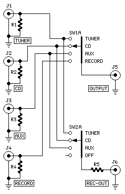 Preamplifier Switching Center Module