Showing posts with label fm. Show all posts
Showing posts with label fm. Show all posts
Saturday, January 18, 2014
9V FM Transmitter
This fm transmitter circuit is a very simple and require few external components and operates in FM band above 100 MHz.This fm transmitter needs to be powered from a 9 volts battery or from another 9 volts regulated power supply .The tuned coil L1, has two output tapping for the antenna connection, marked "A" and "B".
These are both low-level outputs and you choose which tapping you want to use ( stable low range, or more unstable but higher range). Tap B (2.5%) takes just a very small portion of signal from the oscillator circuit and therefore gives a very frequency stable transmitter. The output level (around 2.5mW) and range are therefore somewhat reduced.Tap A (10%) delivers very much more power (around 10mW) to the antenna load. This gives you a greater range, but at the expense of frequency stability.
9V FM Transmitter Circuit diagram

All component leads should be kept as short as possible. The LINK wire on the PCB should lay flat on the PCB. Use the cutoff from a resistor leg. Antenna length for circuit diagram transmitter varies with frequency for optimum distance: 90MHz 80 cm, 95MHz 75cm, 100MHz 70 cm, 105 MHz 68 cm.The frequency determining elements (L1, C5 and C6) form a simple LC tuned oscillator. The inherent problem with this type of circuit diagram transmitter is that any external load (antenna) will change the operating frequency.
These are both low-level outputs and you choose which tapping you want to use ( stable low range, or more unstable but higher range). Tap B (2.5%) takes just a very small portion of signal from the oscillator circuit and therefore gives a very frequency stable transmitter. The output level (around 2.5mW) and range are therefore somewhat reduced.Tap A (10%) delivers very much more power (around 10mW) to the antenna load. This gives you a greater range, but at the expense of frequency stability.
9V FM Transmitter Circuit diagram
All component leads should be kept as short as possible. The LINK wire on the PCB should lay flat on the PCB. Use the cutoff from a resistor leg. Antenna length for circuit diagram transmitter varies with frequency for optimum distance: 90MHz 80 cm, 95MHz 75cm, 100MHz 70 cm, 105 MHz 68 cm.The frequency determining elements (L1, C5 and C6) form a simple LC tuned oscillator. The inherent problem with this type of circuit diagram transmitter is that any external load (antenna) will change the operating frequency.

Friday, December 20, 2013
Tracking FM Transmitter Schematics
FM tracer was prepared using the LM3909 IC and some supporting components. 1.5V FM trackers This will provide an indicator of revenue sources by providing a signal emitted by the LED. FM tracking uses a source voltage of the battery cell and fruit consumption current is 3.7 mA.
After completion of assembling Tracker FM 1.5V, then the next step is setting the operating frequency of the FM tracker is, for convenience we can use the FM receiver and adjust the working frequency FM 1.5V Tracking (tracking transmitter) by regulating C3.Have been obtained if the working frequency Tracking FM 1.5V (tracking transmitter) then the corresponding LED will light emitted by the transmitter information such as sound through an FM receiver is terdengan. 1.5V FM tracker (tracking transmitter) can use a regular 12-inch antenna. Playing and learning electronics that will be happy,
1.5 Volt Tracking FM circuit (Tracking Transmitter)

Circuit Description 1.5 Volt Tracking FM (Tracking Transmitter)
- For stability, use a NPO types for C2 & C4.
- Tolerance for R1 should be 1 or 2%.
- Frequency range is usually 87-109Mhz FM.
- Email wire used in wire coil is made of hookup 22 ga, like the solid Bell phone wire.
Tuesday, December 3, 2013
Filter freq dirty from an fm transmitter
Low pass filter is a circuit to filter freq dirty from an fm transmitter. so we get a clean signal. and can maximize the output power generated from the booster. low pass filter is capable to 150 watts. in this post . file [lay] that can only be opened with software sprint layout. for those interested please download here.

Thursday, November 21, 2013
FM Moulator with IC 555
FM Modulator circuit is a simple FM modulation circuit using IC 555, where the resulting modulated signal has a tenuous meeting depends on the signal frequency information.

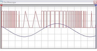
The resulting signal can be spelled out quite nice and stable so that the result will be more perfect. No winding or inductor in series modulator, so you do not need to bother to make a winding and calculate the value of the coil that you created it. With this circuit the desired value of frequency modulation can be obtained easily by calculating the frequency of IC 555 in general, which is determined by the resistor 6.8 K and 3.3 K and 0.1 UF capacitor. To obtain the other frequencies of your stay replace one or all three components.
Actually fm modulator ic 555 circuit is very simple though, but I think it reliable enough to handle a simple application purposes that do not require a big power or a very high frequency. But if you want more power you can add the RF amplifier circuit at the output of this circuit. Thus, the results of modulated signal can be amplified with the help of a series of supporters. In accordance with my experimental series modulators can work well at frequencies below the MHz range, because it is not IC IC 555 which is devoted to support of a very high frequency. You can use oscilltor transistor circuit, XTAL or others if you need a very high frequency.
The difference circuit with IC 555 on the multivibrator circuit in general is the use of pin 5, on the FM Modulator circuit is pin 5 of IC 555 is used as input information signal, which in turn will influence the shape of the output signal (modulated). But in applying this 5 pin multivibrator functions normally associated with 0.01 UF capacitor or left alone.
Subscribe to:
Posts (Atom)