Showing posts with label with. Show all posts

Friday, October 24, 2014

Simple Clock pulse Generator with CD4049

If you want to generate clock with CD4049 CMOS you can do as the follow picture.The typical resister values is 100K and Capacitor is 0.01-0.1uF.The output frequency is about 1/1.1RC ___Hz

Read More..

Saturday, October 11, 2014

Build a 1 2 36V 5A Adjustable Power Supply with LM317

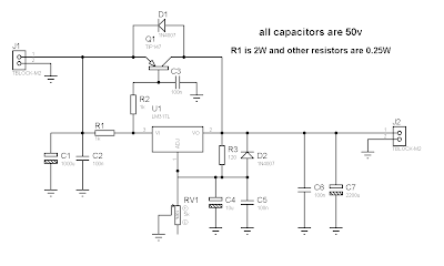
Build a 1.2-36V 5A Adjustable Power Supply circuit diagram with LM317. This circuit is a simple power supply circuit. 1.2 - 36V adjustable bench power supply with 5A of output current. Max input voltage is 37V and output is adjustable via potentiometer between 1.2 up to 36 volts. TIP147 PNP darlington transistor boosts the current of LM317 from 100mA to 5A. LM317 is the most useful and inexpensive adjustable regulator and for this circuit you can also use LM317 L that can give 100mA, thats enough for transistor bias. 

 1.2-36V 5A Adjustable Power Supply Circuit Diagram

1.2-36V 5A Adjustable Power Supply with LM317

 D1 and D2 are protection diodes because when you turn the circuit off the output capacitors are discharging and can damage the transistor or regulator. 100nf capacitors are in parallel with electrolytic capacitors to remove high frequency noise because large value electrolytic have large ESR and ESL and cant remove high frequency noise.
Read More..

Thursday, February 27, 2014

Electronic Circuits for the Evil Genius 2nd Edition 64 Lessons

WE CASUALLY ACCEPT ELECTRONICS in our everyday world. Those who don’t understand how it works are casually obedient. Those who take the time to learn electronics are viewed as geniuses. Do you want to learn how to control the power of electronics? This text provides a solid introduction to the field of electronics, both analog and digital. Electronic Circuits for the Evil Genius is based on practical projects that exercise the genius that exists in all of us. Download ebook for full details and articles.

File Type: PDF
File Size:15MB
Total Pages: 321

PART ONE Components
  1. Components
  2. Resist If You Must
  3. More Components and Semiconductors
  4. Two Projects and Then Some More
PART TWO Introduction to Digital Electronics
  1. Digital Logic
  2. The First NAND Gate Circuit
  3. Analog Switches for Digital Circuits
  4. The NAND Gate Oscillator
  5. How Do We Understand What We Can’t See? .
  6. Digital Logic Project
PART THREE Counting Systems in Electronics
  1. Introducing an Analog-to-Digital Converter
  2. The 4017 Walking Ring Counter
  3. Running a Seven-Segment Display
  4. Define, Models, and Make Your Own Project
PART FOUR Amplifiers: What They Are and How to Use Them
  1. What Is an Amplifier?
  2. Exploring the Op Amp
  3. Applying the Op Amp: Building the Intercom
  4. Prototype and Models: Patience Has Its Rewards
PART FIVE Appendices
  • Common Component Packaging
  • Capacitors: Reading and Decoding
  • Animations List
  • Glossary.
  • Make Your Own Printed Circuit Boards
Read More..

Sunday, February 9, 2014

Power Supply with principle of UPS

power supply voltage
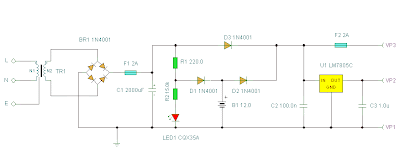
For UPS Power Supply circuit consists of lowering the voltage, rectifier, charger, batery and regulators. The technique is applied from UPS on the power supply is the use of batery and charger is connected dengang direct coupling with a series diode. For more details can be seen with the following image.

Ups power supply schematics
Schematics
The rectifier in the circuit UPS Power Supply For this to function also as a charger via D1. D3 function is to drain-source voltage of the rectifier to the regulator circuit, when the AC voltage source. D2 serves to drain the batery when the source voltage from AC voltage source does not exist. batery configuration and diode D1, D2 and D3 is adopted from the UPS system. may be useful and can provide inspiration on teman2 all in making backups on the system power supply voltage.
Read More..

Saturday, February 8, 2014

Schematic Power Amplifier with IC TDA7370

Here..... this circuit is stereo power amplifier , based on IC TDA7370, its nice Intregated Power amplifier , He does not have hre slightest sound buzzing , although power amplifiers without additional reinforcement , such as filters , tone control, etc.
Voltage                      : 9 to 24 volts
Max. Power Output  : 2 x 20 Watts
Impedance                : 4 Ohms
Read More..

Friday, February 7, 2014

Small Power Amplifier with IC TDA1908

Schematic circuit power amplifier TDA1908 , or you can use IC TDA1908A . The circuit simple and easy to make the line PCB. See circuit and technical instruction below : 

The circuit above can use to the 5.1 surround sound circuit , but you have made 6 circuit and to combine to 1 .  And suitable made to center speakers.
Technical information :
Minimum require voltage :  6 Volts
Maximum require coltage :  30 Volts
Maximum Power output   :  16 Watts
Minimum Power output    :   4  Watts
Read More..

Call Bell with Welcome Indication

Here is a simple call bell circuit that displays a welcome message when somebody presses the call bell switch momentarily. the alphanumeric display can be fitted near the call bell switch. the circuit is built around two 555 ICs (IC1 and IC2), seven KLA511 common-anode alphanumeric displays (DIS1 through DIS7) and a few discrete components. For easy understanding,  the entire circuit can be divided into  two sections: controller and display. the controller section is built around  IC1 and IC2, while the display section is built around alphanumeric displays (DIS1 through DIS7). 

As shown in the circuit, both IC1 and IC2 are wired as monostable  multivibrators having time periods of around 5 seconds and 2 minutes, respectively. You can change the time period of IC1 by changing the values of resistor R12 and capacitor  C3. Similarly, the time period of IC2  can be changed by changing the values of resistor R2 and capacitor C1. Alphanumeric displays DIS1 through DIS7 are wired such that they show ‘WELCOME’ when the output of IC2  goes high. the circuit is powered by a 6V battery. Else, you can use the 6V, 300mA power adaptor that is readily available in the market. the 6V battery or power adaptor provides regulated 6V required to operate the circuit. 

Circuit diagram :
Call Bell with Welcome Indication-Circuit Diagram
Call Bell with Welcome Indication Circuit Diagram
 
A 6V DC socket is used in the circuit to connect the output of the adaptor if you don’t use the battery. Working of the circuit is simple. First, power-on the circuit using switch S2. LED1 glows to indicate presence of power supply in the circuit. Now if you press call bell switch S1  momentarily, it triggers  both the timers (IC1 and  IC2) simultaneously. IC1 produces a high output at its pin 3 for about five seconds. transistor t2 conducts and piezobuzzer PZ1 sounds for about five seconds indicating that there is  somebody at the door. At the same time, IC2  too produces a high out-put at its pin 3 for about two minutes. transistor  t1 conducts to enable the alphanumeric displays. the word ‘WEL-COME’ is displayed  for about two minutes  as DIS1 through DIS7  ground via transistor T1.

If switch S1 is pressed again within these two minutes, piezobuzzer PZ1 again  sounds for five seconds and the display continues to show ‘WEL-COME’. Assemble the complete circuit on a general purpose PCB and house in a small cabinet with call bell switch S1 and LED1 mounted on the front panel. At the rear side of the cabinet, connect a DC socket for the adaptor. Install the complete unit (along with the display) at the entrance of your house. Connect the 6V battery or 6V adaptor for powering the circuit. Configure switch 2 (used to enable/disable the call bell) in a switch board at a suitable location inside your house. If you don’t use a battery, connect the power adaptor to the DC socket on the rear of the cabinet. Close switch S2 only when you want to activate the circuit with  battery. Otherwise, keep it open when the 6V adaptor is in use.
EFY note. 
1. To avoid any shorting  during rain, waterproof the entire circuit assembly including alphanumeric displays (installed at the entrance) by covering it properly.
2.  the complete kit for this circuit is available with EFY associates  kits’n’spares. 

Author : S.C. Dwivedi - Copyright : EFY
Read More..

Led Flasher with the LM3909 IC streampowers

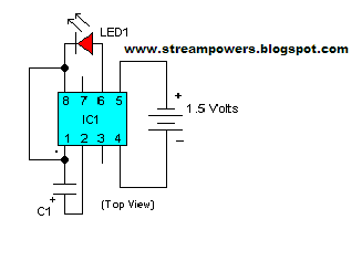
The LM3909 is an integrated circuit (IC) which will flash a light-emitting diode (LED). Using only two extra components and a battery, the circuit is cheap and has a very low current drain from a 1.5 V cell.
The circuit can be used as a novelty flasher, an indicator for a dummy alarm bell box, or it could be attached to a torch so that it could be found easily in the dark! The simple circuit
Led Flasher with the LM3909 IC Diagram
Assembly
The circuit can be built on a small piece of Veroboard (the piece shown in Figure 2 measures 15 holes by 10 strips). Using such a board, follow these instructions.

1. Depending on how far away you want the LED from the circuit board, solder a length of insulated wire to each lead of the LED. Use different colours of insulation – say, red and black, connecting the red lead to the anode (a) lead (the longer one) of the LED, and the black one to the cathode (k). Figure 2 shows these leads.
2. Cut the copper tracks as shown in Figure 2, using a 3 mm (1⁄8 inch) diameter drill, rotated between thumb and forefinger, or use the proper tool. Make absolutely sure that the tracks are completely broken!
3. Fit the IC holder in the correct position, using the cut tracks as guides, and make sure the small notch is facing towards the top of the board. Solder the pins to the copper tracks.
4. Mount the capacitor, positive end to the left, so that the positive lead is soldered to track F, which connects it to pin 2 of the IC; the negative lead is soldered to the right-hand side of track E, this being connected to pin 8 of the IC.
5. Solder on the battery leads, positive to the right, and the extended LED leads, positive downwards.
6. Check the circuit, and hold up the board to a bright light and look carefully for solder bridges between the tracks and pieces of copper swarf which may have escaped your inspection in 2 above! Remove whatever you find.
7. When all seems well, put the IC into the socket, ensuring that the notch or dot on the upper surface of the IC lines up with the notch on the holder. Line up each pin on the IC with the hole below it before pressing gently on the IC with the board supported on a firm surface.
8. Connect the battery; the LED should start to flash. The circuit is complete and working!
If you prefer, the whole circuit (battery included) can be mounted in a small plastic box, with the LED mounted on a clip and protruding through the panel. There are many other possibilities, and it is up to you to find an application for your own use.

Parts list
LM3909 Integrated circuit
IC socket 8-pin DIL BL17T
LED 5 mm diameter WL27E
100 microfarad (#F) Electrolytic capacitor (10 V) FB48C
Battery holder For AA-size cell YR59P
Battery 1.5 V AA cell
Small piece of Veroboard (15 holes by 10 strips)
Small plastic box (if required)
LED clip (if required)
Two lengths of coloured, insulated wire for LED (as required)
Read More..

Tuesday, February 4, 2014

Regulator power supply with op amp

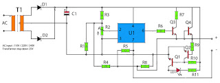
Power supply circuit has a first amplifier using op-amp is IC uA741. Op amp circuit that is used only one, but it also features an adjustable voltage, which is steered by a trimpot resistors. Rtrim will set the input to the IC input on pin 2, so that if the detainee on Rtrim which will be channeled into ic enlarges the output voltage will be small, and otherwise. After the voltage is boosted and filtered and then the voltage will be regulated and boosted again by a NPN transistor.
op-amp regulator power supply
Output voltage 0.5V - 35V
Part List :
Resistor
R1____1K5
R2____1K trim
R3____10K
R4____330R
R5____1K
R6____47R
R7____68R
R8____820R
R9____47K
R10___22K
R11___1K5

Capacitor
C1____10000uF 80V

Transistor
Q1____2N3565
Q2____2N3565
Q3____S9013
Q4____S9013

Diode
D1____1N4007
D2____1N4007
LED1_Red Led

IC
U1____uA741 (op-amp ic)
Read More..

Car Battery Voltmeter with LED Indicator

The circuit was developed to create a voltmeter that will be used to test car batteries while showing an indication using LEDs.

  • Voltmeter – a device or an instrument used for measuring the electrical potential difference between two points of either alternating current or direct current electric circuit.
  • LM324 – has internal frequency compensated for unity gain, large DC voltage gain, wide bandwidth, wide power supply range, very low supply current drain, low input biasing current, low input offset voltage, large output voltage swing and differential input voltage range equal to the power supply voltage.
The voltage of a car battery can be measured with the use of a voltmeter as well as the charge left. A typical car battery voltage delivers around 12.6 V under no load condition and will require charging if the voltage reading is at 11.6 V. The measurement of voltage is best recommended during a high current like running the car head lights into high beam. In case the battery rapidly drops its voltage significantly under load, it would require a replacement.

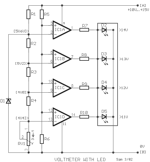
This circuit will function as a comparator and will measure the car battery voltage with an interval or step of 1 V. The voltmeter will be connected across the battery terminals then starting the car. The voltage of the battery should not be measured below 10 V or else it will be considered as low in charge or low in water, since the water level of the battery should be about ¼ of an inch above the plates.

Car Battery Voltmeter with LED Indicator Schematic


Car Battery Voltmeter with LED Indicator

By applying the voltage of the battery in the inverting inputs of the amplifiers, the indicated voltage on the voltmeter is compared with the reference voltages that are produced by the Zener diode D1. The Zener diode is a special kind of diode that permits the flow of current in just one or forward direction as a normal diode, but will also allow in the reverse direction if the voltage is above or larger than a certain value of the breakdown voltage. The measured value is just enough to provide good thermic stability.

The presence of 10K trimmer RV1 is to adjust the degree of voltage that is required or desired while the visual indication will originate from the four LEDs.

R1=1K2
R2-3-4=680R
R5=15K

R6=10K
R7-8-9-10=1K
D1=5V6 /0.5W Zener

D2-3-4-5=LED
IC1=LM324
RV1=10K trimmer

The main use of the car battery voltmeter is to monitor the life and performance of batteries. It can be mounted on the dashboard that shows the battery condition to easily monitor the electrical system voltage while driving. The measurement is done by switching off the engine as well all lights and accessories and switching on the key without starting the engine. The battery is full charge if the voltmeter reads 12 V or more while a voltmeter reading of much less than 12 V signifies the battery is either discharged or failing.
Read More..

Sunday, January 26, 2014

Power amplifier circuit with IC LM386

IC LM386 is working for the amplifier audio circuit with a low power output , range from 0.325 watts to 2 watts with impedance 8 ohm. In this circuit requires voltage of 12 volts to the maximum work, and maximum current 3 Amp.
Components List :
R1=33K / 0,25W
R2=1K / 0,25W
R3=10R / 1W

C1=100n
C2=0,1uF/35V
C3=100uF/16V
C4=220uF/35V
C5=4,7uF/16V
IC1=LM386

Connector Instruction:
X-1  = Input , connect to output
X-2  = Input Ground
X1-1= V+ , 12 Volt DC
X1-2= V-/ Ground
X1-3= Speaker+
X1-4= Speaker-
Read More..

Tuesday, January 21, 2014

15 V output regulated power supply circuit with uA723 and 2N3055

The supply receive from 220 /120/110 Volt AC , then lowered by the transformer . Then receives +20 Volts DC from rectifier / filter section. This applied to pin 11 and 12 of the IC uA723/LM723 , as well as to the collector of the 2N3055 series pass transistor. The output through R1 and R2, providing about 7 V with respect to ground at pin 4. The reference terminal at pin 6 is tied directly to pin 5 , the non inverting input of the error amplifier . For fine trimming the output voltage , a potentiometer can be installed between R1 and R2. A 100-pF capacitor from pin 13 to pin 4 furnishes gain compensation for the amplifier.
Base drive to the 2N3055 pass transistor is furnishes by pin of the uA723. Since desired output of the supply is 1 Ampere, maximum current limit is set to 1,5 Ampere by resistor Rsc whose value is 0,422 Ohm. A 100uF electrolytic capacitor is used for ripple voltage reduction at the output. A 1 kOhm output resistor provides stability for the power supply under no - load conditions. The 2N3055 pass transistor must be mounted on an adequate heatsink.
Read More..

Monday, January 20, 2014

Solid State Relays Circuit with TIL111

Solid state relays are almost everywhere these days, but they are very expensive. So, your efforts to build their own salary. Especially since it’s only a few parts and circuit simple and straightforward. Solid state relay is not really at all relays. There are no “relay” is available only with electronics, connection works. It works well as a relay, you can use low voltage higher and better. “Relay” between 115/220V AC wires in place, although it was customary, the neutral conductor and leave unchanged phases and neutral.

As long as no voltage (left in picture), the phototransistor TIL111 blocks of energy, and thus is not available. To ensure that the base TIL111 is fed to the transmitter (s) through the 1M resistor. This method prevents the base of transistor BC547B will be low and remains biased ‘on’. Collector is low and the gate (g) TIC106M thyristor, which is still in the country, “off”. 4-diode bridge rectifier circuit has no power apart from a small base and collector current BC547B, which is not enough to turn over the 330-ohm resistor TIC226M triac. Current “Load”, is very small.

Solid State Relays Circuit Diagram

With an input voltage, say 5 volts, the diode in the TIL111 lights up and activates the phototransistor. The voltage drop 1MEG ohm resistor in series with 22K resistance increases demand, which block the BC547B transistor. Collector current of the fact that the AC voltage falls below a certain value, which is VA. This ensures a sufficiently large voltage drop across the resistor 330 ohms triac switches ‘on’. The voltage on triac is currently only a few volts, so that practically the whole 115/220 AC voltage on the “Upload”.

The triac is a 100nF capacitor and impedance of 47 ohms, 100nF capacitor for the 330 ohm resistor is to protect the triac to be undesirable distortions caused by small peaks. To create the possibility of this circuit with different voltages to be switched, added BF256A FET. The FET acts as a current source from the source (s) with a gate (g). This means that this FET determines the current TIL111, regardless of the input voltage (up to a certain tolerance, of course). 1N4148 diode is to protect the circuit from reverse polarity.
(Tony: TIL111 is a so-called “optical coupling” with NPN output and can be replaced with NTE3042)

Good point line, as is the separation of AC and DC voltage, so this circuit is used in many applications, about 1.5 kW, when the triac is mounted on the large size of the cooling fins. “M” appears Triac means it’s 600volt type, “D” for 400V. So be sure to go to the M-type. NTE replacement for this circuit are 600volt types which are more than sufficient for our 110/115VAC. Even if you decide to print for this circuit is enough space between the lines AC and non AC these tracks to be close.
Read More..

Tuesday, January 14, 2014

Power Supply with regulation

power supply universalElectronic devices should be powered by direct current supply of DC (direct current) which is stable in order to work properly. The battery or batteries are the source DC power supply is best. However, for applications that require power supplies larger, the source of the battery is not enough.
A major source of power supply is alternating source of AC (alternating current) from power plants. For that needed a power supply device that can convert AC current into DC. In this article presented the principles of the power supply circuit (power supply), linear start from the simplest rectifier circuit to the power supply was regulation.

Power supply is functioning electronic circuit to supply power to other components in perangakat electronics. All electronic components that exist in an electronic device will receive power supply from the power supply. Power supply is very has a very important role in an electronic device. Therefore, without power supply, an electronic device will not work. The common voltage supplied by the power supply is +5 V, +12 V,-5V,-12V.
Large output voltage of power supply also must we adjust the voltage needs burden or our electronic devices. Because, an electronic device will be able to work well if the supply voltage and power to him just like the specifications of these electronic components. (specification can be seen in the datasheet of a component).
simple power supply schematic

Power supply circuit drawing examples above we can replace with our needs. Pictured above is a simple power supply circuit having 78XX LM as a regulator. Type LM 78XX can we replace it according to our needs. If for example we want the output from the power supply is +12 Volts, then we have to change it into LM7812 LM. And also of course we have to input voltage of +12 volt transformer.

Similarly, if we want a voltage of +5 volts. So we have to replace the LM7805 LM 78XX, and the input voltage from the transformer 5Volt (transformer).
Read More..

Monday, January 13, 2014

24V DC Powered Beeper with 4 Separate Inputs

24 Volt DC is a very prevalent voltage used fashionable developed settings. This hobby circuit lower was designed to acknowledge four unlike 24v DC alarm input signals, which are followed by used to drive a single low power beeper. The beeper is a magnetic type with its own oscillator/driver. The four diodes form an “or else” gate so one solitary of the four inputs want cause the beeper to produce blast. A CMOS version of the widely held 555 timer is used to strobe the beeper on and rancid on something like 1Hz.

24V DC Powered Beeper with 4 Separate Inputs Circuit Schematic Diagram

Copyright: Discover Circuits
Read More..

Thursday, January 9, 2014

Low Power Audio Amplifier Circuit with IC TDA2824S

This is stereo audio amplifier with based on ICTDA2824S , Minimum voltage require 3 volts and maximum voltage 17 volts . Maximum output power 2 X 2 Watt , its low power amplifier. Output impedance  4 ohm. see schematic audio below :
Read More..

Thursday, December 26, 2013

600 Watt Quasi Amplifier With Mosfet IRFP460

ACTK 400/600 Watt
Two versions of a robust module capable of delivering high powwer for extended periods.  The Actrk400 uses 6 n-channel Mosfets in the output stage to deliver around 400 watts into 4 ohms while the Actrk600 uses 12 n-channel Mosfets in the output stage to deliver power in excess of 600 watts into 4 ohms.  One constructor has achieved almost 900 watts with the Actrk600 layout using 12 IRFP460 Mosfets.

600 Watt Quasi Amplifier With Mosfet IRFP460

Read More..

Monday, December 23, 2013

Multiplexer with CMOS IC 4556

In addition to the family of TTL ICs that support the function of a multiplexer is a family of CMOS ICs.

Despite the fact it is the family of TTL ICs that support more functions than the CMOS multiplexer. For the working principle of the multiplexer IC CMOS family is actually tantamount to a multiplexer circuit, or IC TTL logic gates. That should be all referring to the real multiplexer function, namely the determination of output lines which represent the number of input lines. The use of symbols is possible between TTL and CMOS IC has a different but actually run the same rules. For your reference if you are interested in using family of CMOS IC 4556 series in particular, I include also the truth table below:


INPUT
OUTPUT
E
A0
A1
O0
O1
O2
O3
L
L
L
L
H
H
H
L
H
L
H
L
H
H
L
L
H
H
H
L
H
L
H
H
H
H
H
L
H
X
X
H
H
H
H
L = LOW
H = HIGH
Read More..

Sunday, December 22, 2013

Audio Amplifier Circuits 10W with Bass boost

Parts:
P1 22K Log.Potentiometer (Dual-gang for stereo)
P2 100K Log.Potentiometer (Dual-gang for stereo)
R1 820R 1/4W Resistor
R2,R4,R8 4K7 1/4W Resistors
R3 500R 1/2W Trimmer Cermet
R5 82K 1/4W Resistor
R6,R7 47K 1/4W Resistors
R9 10R 1/2W Resistor
R10 R22 4W Resistor (wirewound)
C1,C8 470nF 63V Polyester Capacitor
C2,C5 100uF 25V Electrolytic Capacitors
C3,C4 470uF 25V Electrolytic Capacitors
C6 47pF 63V Ceramic or Polystyrene Capacitor
C7 10nF 63V Polyester Capacitor
C9 100nF 63V Polyester Capacitor
D1 1N4148 75V 150mA Diode
IC1 NE5532 Low noise Dual Op-amp

Q1 BC547B 45V 100mA NPN Transistor
Q2 BC557B 45V 100mA PNP Transistor
Q3 TIP42A 60V 6A PNP Transistor
Q4 TIP41A 60V 6A NPN Transistor
J1 RCA audio input socket
Power supply parts:
R11 1K5 1/4W Resistor
C10,C11 4700uF 25V Electrolytic Capacitors
D2 100V 4A Diode bridge
D3 5mm. Red LED
T1 220V Primary, 12 + 12V Secondary 24-30VA Mains transformer
PL1 Male Mains plug
SW1 SPST Mains switch
Comments:
This design is based on the 18 Watt Audio Amplifier, and was developed mainly to satisfy the requests of correspondents unable to locate the TLE2141C chip. It uses the widespread NE5532 Dual IC but, obviously, its power output will be comprised in the 9.5 - 11.5W range, as the supply rails cannot exceed ±18V.
As amplifiers of this kind are frequently used to drive small loudspeaker cabinets, the bass frequency range is rather sacrificed. Therefore a bass-boost control was inserted in the feedback loop of the amplifier, in order to overcome this problem without quality losses. The bass lift curve can reach a maximum of +16.4dB @ 50Hz. In any case, even when the bass control is rotated fully counterclockwise, the amplifier frequency response shows a gentle raising curve: +0.8dB @ 400Hz, +4.7dB @ 100Hz and +6dB @ 50Hz (referred to 1KHz).
Notes:
Can be directly connected to CD players, tuners and tape recorders.
Schematic shows left channel only, but C3, C4, IC1 and the power supply are common to both channels.
Numbers in parentheses show IC1 right channel pin connections.
A log type for P2 ensures a more linear regulation of bass-boost.
Dont exceed 18 + 18V supply.
Q3 and Q4 must be mounted on heatsink.
D1 must be in thermal contact with Q1.
Quiescent current (best measured with an Avo-meter in series with Q3 Emitter) is not critical.
Set the volume control to the minimum and R3 to its minimum resistance.
Power-on the circuit and adjust R3 to read a current drawing of about 20 to 25mA.
Wait about 15 minutes, watch if the current is varying and readjust if necessary.
A correct grounding is very important to eliminate hum and ground loops. Connect in the same point the ground sides of J1, P1, C2, C3 &C4. Connect C9 at the output ground.
Then connect separately the input and output grounds at the power supply ground.
Technical data:
Output power: 10 Watt RMS @ 8 Ohm (1KHz sinewave)
Sensitivity: 115 to 180mV input for 10W output (depending on P2 control position)
Frequency response: See Comments above
Total harmonic distortion @ 1KHz: 0.1W 0.009% 1W 0.004% 10W 0.005%
Total harmonic distortion @ 100Hz: 0.1W 0.009% 1W 0.007% 10W 0.012%
Total harmonic distortion @10KHz: 0.1W 0.056% 1W 0.01% 10W 0.018%
Total harmonic distortion @ 100Hz and full boost: 1W 0.015% 10W 0.03%
Max. bass-boost referred to 1KHz: 400Hz = +5dB; 200Hz = +7.3dB; 100Hz = +12dB; 50Hz = +16.4dB; 30Hz = +13.3dB

Read More..

Thursday, December 19, 2013

Bouncless Switch with NE555

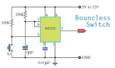
Bouncless Switch with NE555 Circuit Diagram
Bouncless Switch with NE555 Circuit Schematic
Application IC 555 Timer intended for tranquil Timer circuit.
Output pin 3 pluse 0.1s. Control by energy S1.
Volt supply pin 8 = 12Volt
Read More..