Showing posts with label 2. Show all posts
Showing posts with label 2. Show all posts
Saturday, October 11, 2014
Build a 1 2 36V 5A Adjustable Power Supply with LM317
Build a 1.2-36V 5A Adjustable Power Supply circuit diagram with LM317. This circuit is a simple power supply circuit. 1.2 - 36V adjustable bench power supply with 5A of output current. Max input voltage is 37V and output is adjustable via potentiometer between 1.2 up to 36 volts. TIP147 PNP darlington transistor boosts the current of LM317 from 100mA to 5A. LM317 is the most useful and inexpensive adjustable regulator and for this circuit you can also use LM317 L that can give 100mA, thats enough for transistor bias.
1.2-36V 5A Adjustable Power Supply Circuit Diagram
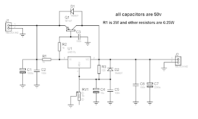
D1 and D2 are protection diodes because when you turn the circuit off the output capacitors are discharging and can damage the transistor or regulator. 100nf capacitors are in parallel with electrolytic capacitors to remove high frequency noise because large value electrolytic have large ESR and ESL and cant remove high frequency noise.

Monday, December 23, 2013
2 Transistor Transmitter Schematic
A compact 2 transistor transmitter for use at VHF frequencies.
2 Transistor Transmitter Schematic Circuit Diagram

Notes:
Transistor T1 works as an audio preamplifier, gain is fixed at approximately R2/R1 or 100 times. The audio input is applied at the points LF in (on the diagram). P1 works as gain control. After amplification this audio signal now modulates the transmitter built around T2. Frequency is tunable using the trimmer CT and L1 is made using 3 turns of 1mm copper wire wound on a 5mm slug. The modulated signal passes via C6 to the antenna. A dipole can be made using 2 lengths of 65cm copper pipe. A DC power supply in the range 3 to 16 volts is required.
2 Transistor Transmitter Schematic Circuit Diagram
Transistor T1 works as an audio preamplifier, gain is fixed at approximately R2/R1 or 100 times. The audio input is applied at the points LF in (on the diagram). P1 works as gain control. After amplification this audio signal now modulates the transmitter built around T2. Frequency is tunable using the trimmer CT and L1 is made using 3 turns of 1mm copper wire wound on a 5mm slug. The modulated signal passes via C6 to the antenna. A dipole can be made using 2 lengths of 65cm copper pipe. A DC power supply in the range 3 to 16 volts is required.
Wednesday, December 18, 2013
10 2 Surround Sound Systems
10.2 channel surround is the yet to come surround sound machinery so as to residential by THX corporation, the pet name itself, 10.2 is an cutting edge version of 5.1 tools but 10.2 is twice like mild as 5.1. concerning a 10.2 surround sound 14 channels are used. This includes five front speakers, five surround channels, two LFE and two heights, plus the addition of a instant associate-woofer. This equipment is considered as impending TRUEHD.The Diagram of a 10.2 TrueHD setup is publicized less than.
 |
| 10.2 Surround Sound Systems |
1 3 12 2 VDC Variable Power Supply
Power supply circuit to generate output below were variations between 1.3V DC to 12.2V DC with 1A current.

Read More..
In addition, the power supply circuit is also equipped with over-current protection or shield against belebih flow. Power supply circuit is very simple, but the quality is quite good, made her basiccally regulator IC LM723 is a fairly legendary.
Friday, December 13, 2013
2 X 2 4 2 x 4 5 17 Watt Power Amplifier
Amplifier circuit here is all based on the ic in the gains. Three IC TA7230P, TA7236P, TA7237AP is intregated circuit (IC) which was applied to the power amplifier. Each IC has a different output, different input voltage, all IC TA7230P, TA7236P, TA7237AP is manufactured by Toshiba.
Read More..
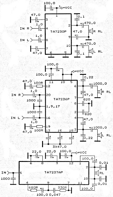 |
TA7230P, TA7236P, TA7237AP amplifier schematic |
Sunday, December 8, 2013
Adjustable Power Supply 1 2 – 30V 5A using LM338
If you want to a variable dc voltage power supply circuit during 1.2V to 30Vdc and can provide a current maximum to 5A.
We may be have the many ways such as: to be modified the LM317 Variable Regulator 0-30V 1A by add the power transistor MJ2955 in circuit following Power supply regulator 1.2V-20V and 3V-6V-9V-12V 3Amp or will build the Variable dc regulator 0-30V 5A circuit to be well as well, But these methods. Rather cumbersome and wasting too money.

However we can build this circuit easily and cheap, By using the packages IC No. LM338 only one, Similar to the LM317 IC number, but it can supply up to 5A, as the circuit shown in Fig.
How this circuit works
-The transformer T1 converts the AC 220V to 24 Vac, so be rectified the current by the bridge diode rectifier BD1 – 10A 400V. Until DCV has come out that the filter capacitor C1 is equal to 35 volt.
-The IC1 is the heart of the operation of this circuit. By the voltage output value obtained from the IC depends on the voltage value at the Adj pin of IC1, or can be varied by adjusting the VR1.
-However output voltage will be approximately equal to 1.25+1.25VR1/R1
The output voltage at the output pin of the IC1 is a more powerful filter with the capacitor C3.
Friday, December 6, 2013
TDA2005 2 X 20 Watt Power Amplifier
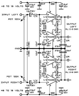
This time, there is a series of audio amplifer 20W as well, but using IC TDA 2005 as a series of his base amplifier.
The series of 2x20 Watt Audio Power Amplifier using TDA2005 can you see in the picture below.
The series of 2x20 Watt Audio Power Amplifier using TDA2005 can you see in the picture below.
Technical Data:
Performance of TDA2005M: (for this circuit); At 4.14 V supply voltage: 2 x 20 watts (stereo) into 4 Ohms.
Distortion: Approx. 0.2% at 4 Watts into 4 ohm load.Frequency Range: Approx. 20 Hz to 22 KHz.
Input Sensitivity: Approx. maximum 150 mV rms. .
Power supply: + 8 to 18 volts, approx. 3.5 Amps maximum per channel.
Wednesday, November 27, 2013
2 X 1 8 Watt stereo low power amplifier circuit
This is Low power amplifier , based on IC TDA2824 product of Philips. Maximum output is about 2 X 1,8 Watt , these include low output amplifier type. Minimum required voltage 3 Volts and maximum voltage of 18 volts DC.

Spec :
- Supply Voltage : 3 - 18 Volts
- Power Output : 2 x 1,3 Watts
- RL impedance : 4 Ohms
- Frequency responses : 30Hz -18kHz
- Quiescent current : 6 mA
Subscribe to:
Posts (Atom)