Showing posts with label adjustable. Show all posts
Showing posts with label adjustable. Show all posts
Friday, October 24, 2014
Ni Cd and Ni MH Adjustable constant current Circuit Diagram
This is a battery charger circuit with adjustable current for Ni-MH or Ni-Cd. It can be used for a constant current power, which can be set to any value from a few milliamps to about 500 mA. The maximum current is 500 mA, because that is the limit of transistor BC140. The input voltage must be above 5.25V output voltage, this is due to losses as 1.25V current limit and approximately 4V regulator.
Battery Charger Ni-Cd and Ni-MH Adjustable constant current Circuit Diagram
Battery Charger Ni-Cd and Ni-MH Adjustable constant current Circuit Diagram

The LM317 regulator is used, it should have a sink.
Components
R1 100Ω resistor
VR1 trimpot or potentiometer 500Ω
Capacitor C1 0.1μF
C2 Capacitor 0.01μF
Diode D1 1N4001
Q1 Transistor BC140
IC1 Voltage Regulator LM317

Friday, October 17, 2014
Adjustable Duty Cycle
The circuit shown here can be used to convert a digital input signal having any desired duty cycle into a output signal having a duty cycle that can be adjusted between 10% and 80% in steps of 10%. The circuit is built around a 74HC4017 decade Johnson counter IC. Individual pulses appear on the ten outputs (Q0–Q9) of this IC at well-defined times, depending on the number of input pulses (see the timing diagram). This characteristic is utilised in the circuit. The selected output is connected via a jumper to the Reset input (MR, pin 2) of a 74HC390 counter. A High level resets the output signals of the 74HC390 counter. Q9 of the 74HC4017 is permanently connected to the CP0 input of the counter to set the Q0 output of the 74HC390 (pin 3) High on its negative edge.

As can be seen from the timing diagram, which shows the signals for a duty cycle of 30% as an example, this produces a signal with exactly the desired duty cycle. The circuit cannot be used to produce a duty cycle of 10% (which would be equivalent to taking the signal directly from the Q0 output of the 74HC4017) or 90%. In both cases, the edges of the pulses used for the count input (CP0) and the asynchronous reset input (MR) of the 74HC390 would coincide, with the result that the output state of the 74HC390 would not be unambiguously defined. The input frequency must be ten times the desired output frequency.

If the second half of the 74HC390 is wired as a prescaler, a prescaling factor of 2, 5 or 10 can be achieved, thus allowing the ratio of the of input frequency to the output frequency to be 20, 50 or 100. If the circuit is built using components from the 74HC family, it can be operated with supply voltages in the range of 3–5 V.
Saturday, October 11, 2014
Build a 1 2 36V 5A Adjustable Power Supply with LM317
Build a 1.2-36V 5A Adjustable Power Supply circuit diagram with LM317. This circuit is a simple power supply circuit. 1.2 - 36V adjustable bench power supply with 5A of output current. Max input voltage is 37V and output is adjustable via potentiometer between 1.2 up to 36 volts. TIP147 PNP darlington transistor boosts the current of LM317 from 100mA to 5A. LM317 is the most useful and inexpensive adjustable regulator and for this circuit you can also use LM317 L that can give 100mA, thats enough for transistor bias.
1.2-36V 5A Adjustable Power Supply Circuit Diagram
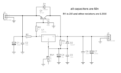
D1 and D2 are protection diodes because when you turn the circuit off the output capacitors are discharging and can damage the transistor or regulator. 100nf capacitors are in parallel with electrolytic capacitors to remove high frequency noise because large value electrolytic have large ESR and ESL and cant remove high frequency noise.
Thursday, December 26, 2013
6 12 Volt Adjustable Power Supply Circuit

Power Supply has an adjustable output with a range of 6-12 VDC. The part that serves as a power regulator is Q1 TIP31. Then the controller output voltage is a voltage divider composed of R3, R4, VR1 and R2 provide bias to the base of Q2 to Q1 mengentrol power regulator. In a series of power supply is mounted 5.1 V zener diode which serves to make the minimum limit the output voltage with Q2.
 |
| Adjustable Power Supply with transistor circuit |
Power Supply With transistor circuit is quite simple and can be made with the PCB holes, so for those who want to try to directly mempraktikannya. May the power supply circuit can be useful for readers, especially for friends who need a power supply circuit with the regulator transistor.
Saturday, December 21, 2013
Adjustable switching power supply
 |
Switching Regulator L4970 series include not complicated to make his own, which need to be considered is the IC L4970 require sufficient cooling to operate in an optimal and durable. Adjustable Switching Regulator L4970 series are complete can be seen in thethe following figure .
 |
| Adjustable switching power supply schematics |
To set the output voltage range Adjustable Switching Regulator L4970 can be in control by adjusting the potentiometer 18KOhm tus.
Sunday, December 8, 2013
Adjustable Power Supply 1 2 – 30V 5A using LM338
If you want to a variable dc voltage power supply circuit during 1.2V to 30Vdc and can provide a current maximum to 5A.
We may be have the many ways such as: to be modified the LM317 Variable Regulator 0-30V 1A by add the power transistor MJ2955 in circuit following Power supply regulator 1.2V-20V and 3V-6V-9V-12V 3Amp or will build the Variable dc regulator 0-30V 5A circuit to be well as well, But these methods. Rather cumbersome and wasting too money.

However we can build this circuit easily and cheap, By using the packages IC No. LM338 only one, Similar to the LM317 IC number, but it can supply up to 5A, as the circuit shown in Fig.
How this circuit works
-The transformer T1 converts the AC 220V to 24 Vac, so be rectified the current by the bridge diode rectifier BD1 – 10A 400V. Until DCV has come out that the filter capacitor C1 is equal to 35 volt.
-The IC1 is the heart of the operation of this circuit. By the voltage output value obtained from the IC depends on the voltage value at the Adj pin of IC1, or can be varied by adjusting the VR1.
-However output voltage will be approximately equal to 1.25+1.25VR1/R1
The output voltage at the output pin of the IC1 is a more powerful filter with the capacitor C3.
Sunday, December 1, 2013
6 12 Volt Adjustable Power Supply Circuit
Power Supply has an adjustable output with a range of 6-12 VDC. The part that serves as a power regulator is Q1 TIP31. Then the controller output voltage is a voltage divider composed of R3, R4, VR1 and R2 provide bias to the base of Q2 to Q1 mengentrol power regulator. In a series of power supply is mounted 5.1 V zener diode which serves to make the minimum limit the output voltage with Q2.
|
| Adjustable Power Supply with transistor circuit |
Power Supply With transistor circuit is quite simple and can be made with the PCB holes, so for those who want to try to directly mempraktikannya. May the power supply circuit can be useful for readers, especially for friends who need a power supply circuit with the regulator transistor.
Subscribe to:
Posts (Atom)