Showing posts with label supply. Show all posts
Showing posts with label supply. Show all posts
Friday, October 24, 2014
8 Amp Regulated Power Supply circuit Diagram
This power supply is powered by a transformer operating from 120 Vac on the primary and providing proximately 20 Vac on the primary, and providing approximately 20 Vac on the secondary. Four 10-A diodes with a 100 PIV rating are used in a full-wave bridge rectifier.
8-Amp Regulated Power Supply Circuit Diagram

8-Amp Regulated Power Supply Circuit Diagram

A 10,000 ^F/36 Vdc capacitor completes the filtering, providing 28 Vdc. The dc voltage is fed to the collectors of the Darlington connected 2N3055s. Base drive for the pass transistors is from pin 10 of the µ723 through a 200 ohm current limiting resistor, Rl. The reference terminal (pin 6) is tied directly to the non-inverting input of the error amplifier (pin 5), providing 7.15 V for comparison. Link
The inverting input to the error amplifier (pin 4) is fed from the center arm of a 10 k ohm potentiometer connected across the output of the supply. This control is set for the desired output voltage of 13.8 V. Compensation of the error amplifier is accomplished with a 500 pF capacitor connected from pin 13 to pin 4. If the power supply should exceed 8 A or develop a short circuit, the µ723 regulator will bias the transistors to cutoff and the output voltage will drop to near zero until the short circuit condition is corrected.
The inverting input to the error amplifier (pin 4) is fed from the center arm of a 10 k ohm potentiometer connected across the output of the supply. This control is set for the desired output voltage of 13.8 V. Compensation of the error amplifier is accomplished with a 500 pF capacitor connected from pin 13 to pin 4. If the power supply should exceed 8 A or develop a short circuit, the µ723 regulator will bias the transistors to cutoff and the output voltage will drop to near zero until the short circuit condition is corrected.

Monday, October 20, 2014
High LASER Power Supply
If you have ever worked with lasers, you know how fun and interesting it can be, you also know how expensive it can be. The high voltage power supplies for the laser tubes are often more expensive then the tubes themselves. This supply can be built with commmon parts, most of which you probably already have in your junk box. The secret is the transformer used. It is a common 9V 1A unit, connected backwards for step up.
Please note that some people may have trouble with this supply. This is due to the slight difference in transformers.

Schematic

Parts
| Part | Total Qty. | Description | Substitutions |
R1 | 1 | 10 Ohm 10W Or Greater Resistor | |
R2 | 1 | Ballast Resistor, See "Notes" | |
D1, D2, D3 | 3 | 1N4007 Silicon Diode | |
C1, C2, C3 | 3 | 0.1 uF 2000V Capacitor | |
T1 | 1 | 9V 1A Transformer | |
S1 | 1 | 115V 2A SPST Switch | |
MISC | 1 | Case, Wire, Binding Posts (for output), Line Cord |
Notes
1. T1 is an ordinary 9V 1A transformer connected backwards for step up.
2. R1 MUST be installed on a LARGE heatsink. A good heatsink is the metal case the supply is built in.
3. R2 Protects the laser tube from excess current. It should be soldered directly to the anode terminal on the tube. To find R2, start with a 500K 10W resistor and work down until the tube lights and remains stable.
4. If you have trouble with the tube not starting easily, use a longer anode lead that is wrapped around the tube.
5. Depending on the transformer you use, the circuit may or may not work. I cannot guarantee the operation of this circuit. Build at your own risk.
Now 0 to 40V Lab Power Supply
A very lab adjustable power supply that can provide an output voltage between 0 and 60 volts can be designed using this circuit diagram . This lab power supply can be designed with LM723 chip or for higher output voltages, with L146 .Output current is also adjustable, but once established, is always effective. Table 1 shows the values to be modified to have three different versions of the maximum output voltage (30, 40 and 60 V).

Electrical diagram below shows the alternative 40 V / 0.8 using L146 chip because it can stabilize higher output voltage, much better than the LM723. Normally, 2 V is the minimum voltage stabilized that even an integrated circuit can provide. Resistive network R3, R4 and R5, R6 "kill" this restriction so that output can be set to 0 V with potentiometer P2.

Depending on the output requirements, will be decided on the type and the semiconductor capacitors to be used. Output current must be limited so as to keep power dissipation of 40 W. T3 under maximum output current for 40 V version is 0.8 A. It can connect two parallel 2N3055 transistors (with emitter resistors) to double the current output, but in this case requires a 2 A transformer
Saturday, October 11, 2014
Build a 1 2 36V 5A Adjustable Power Supply with LM317
Build a 1.2-36V 5A Adjustable Power Supply circuit diagram with LM317. This circuit is a simple power supply circuit. 1.2 - 36V adjustable bench power supply with 5A of output current. Max input voltage is 37V and output is adjustable via potentiometer between 1.2 up to 36 volts. TIP147 PNP darlington transistor boosts the current of LM317 from 100mA to 5A. LM317 is the most useful and inexpensive adjustable regulator and for this circuit you can also use LM317 L that can give 100mA, thats enough for transistor bias.
1.2-36V 5A Adjustable Power Supply Circuit Diagram
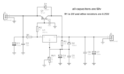
D1 and D2 are protection diodes because when you turn the circuit off the output capacitors are discharging and can damage the transistor or regulator. 100nf capacitors are in parallel with electrolytic capacitors to remove high frequency noise because large value electrolytic have large ESR and ESL and cant remove high frequency noise.
How to Repairing Switching Power Supply
Up to date power supply are renowned as "switching controller power supply." In most swapping supply, the 110 volt AC input is first rectified by two diodes and filtered by a pair of capacitors. This conceives two high- voltage causes; one positive and the other negative. A pair of transistors is then utilized to switch these high voltage supply over the primary winding of a transformer.
This switching activity is very fast. A usual switching pace is around 40,000 circuits per second or 40KHz. An integrated circuit is commonly utilised to control the transistors. This IC not only controls the pace at which the transistors are swapped, but furthermore controls the amount of time that each transistor is energized. The yield voltage of the power supply is very resolute by the "on" time of the transistors. If the transistors are hold on for a longer time span of time, the output voltage of the provide will rise, while shorter times smaller the yield voltage. This is renowned as "pulse-width modulation."
Power Supply

Sunday, February 9, 2014
Low ripple power supply schematic
Simple schematic above is a circuit of power supply that can operate at high current with very small ripple voltage. How it works similiar to the high power class AB amplifiers, with the same quality. T1,T2 ,and R2 can also be called a power NPN-Darlington transistor. ZD1 and R1 as a supplier of voltage on the transistor base and filtered by C2. ZD1 can be slected with formulated (Figure 1.0) . For the C2 can be selected in accordance with the degree of smoothness as its value is effectively combined with the multiplied gain of the Transistor T1 and T2, assumsing minimum hfe for T1 and T2 , C=100x15(T1) x 25 (T2) = 37,000uF, adjust the voltage C2 with the input voltage, but must be higher than input voltage.
Part List :R1 = 2K2R2 = 56RR3 = 10KC1 = 1500uFD1-D4 = Didode 6AT1 = 2N3054T2 = 2N3055

 |
| Figure 1.0 |
Power Supply with principle of UPS

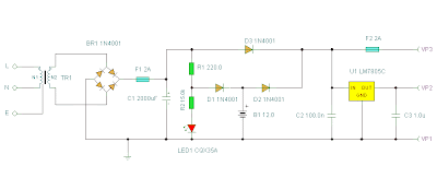
For UPS Power Supply circuit consists of lowering the voltage, rectifier, charger, batery and regulators. The technique is applied from UPS on the power supply is the use of batery and charger is connected dengang direct coupling with a series diode. For more details can be seen with the following image.
 |
| Schematics |
The rectifier in the circuit UPS Power Supply For this to function also as a charger via D1. D3 function is to drain-source voltage of the rectifier to the regulator circuit, when the AC voltage source. D2 serves to drain the batery when the source voltage from AC voltage source does not exist. batery configuration and diode D1, D2 and D3 is adopted from the UPS system. may be useful and can provide inspiration on teman2 all in making backups on the system power supply voltage.
Wednesday, February 5, 2014
Power Supply Diagram for tube amplifier
Power supply for EL-34 tube is specially designed for the purposes of power supply at the push-pull amplifier with EL-34 tube as in article 35 Watt Tube Power Amplifier Push Pull before.
Power supply for EL-34 tube amplifier is made with transformers CT and 2 pieces diode as rectifier. Mechanical filters are applied in the power supply uses 3 levels. Power supply for tube power amplifier can deliver output voltages +220 VDC. Circuit details can be seen in the following figure.
Power supply for EL-34 tube amplifier is made with transformers CT and 2 pieces diode as rectifier. Mechanical filters are applied in the power supply uses 3 levels. Power supply for tube power amplifier can deliver output voltages +220 VDC. Circuit details can be seen in the following figure.

The above power supply circuit has a high output voltage so that need to be considered in the manufacture and perakitanya because electricity can tesengat (stun). Power Supply For Tube Power Amplifier With Diode EL-34 was created specifically for the power amplifier tube push pull EL-34.
Tuesday, February 4, 2014
Regulator power supply with op amp
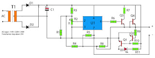
Power supply circuit has a first amplifier using op-amp is IC uA741. Op amp circuit that is used only one, but it also features an adjustable voltage, which is steered by a trimpot resistors. Rtrim will set the input to the IC input on pin 2, so that if the detainee on Rtrim which will be channeled into ic enlarges the output voltage will be small, and otherwise. After the voltage is boosted and filtered and then the voltage will be regulated and boosted again by a NPN transistor.
 |
| Output voltage 0.5V - 35V |
Resistor
R1____1K5
R2____1K trim
R3____10K
R4____330R
R5____1K
R6____47R
R7____68R
R8____820R
R9____47K
R10___22K
R11___1K5
Capacitor
C1____10000uF 80V
Transistor
Q1____2N3565
Q2____2N3565
Q3____S9013
Q4____S9013
Diode
D1____1N4007
D2____1N4007
LED1_Red Led
IC
U1____uA741 (op-amp ic)
Thursday, January 30, 2014
Most Power Supply for Amplifier
Power supply
As with most power amplifiers, the ±60 V power supply need not be regulated. Owing to the relatively high power output, the supply needs a fairly large mains transformer and corresponding smoothing capacitors—see circuit diagram below.
 |
| Note that the supply shown is for a mono amplifier; a stereo outfit needs two supplies. |
The power supply is straightforward, but can handle a large current. Voltage acserves as drive for the power-on delay circuit. The transformer is a 625 VA type, and the smoothing capacitors are 10 000 µF, 100 V electrolytic types. The bridge rectifier needs to be mounted on a suitable heat sink or be mounted directly on the bottom cover of the metal enclosure.. The transformer needs two secondary windings, providing 42.5 V each. The prototype used a toroidal transformer with 2x40 V secondaries. The secondary winding of this type of transformer is easily extended: in the prototype 4 turns were added and this gave secondaries of 2x42.5 V.
Tuesday, January 21, 2014
15 V output regulated power supply circuit with uA723 and 2N3055

The supply receive from 220 /120/110 Volt AC , then lowered by the transformer . Then receives +20 Volts DC from rectifier / filter section. This applied to pin 11 and 12 of the IC uA723/LM723 , as well as to the collector of the 2N3055 series pass transistor. The output through R1 and R2, providing about 7 V with respect to ground at pin 4. The reference terminal at pin 6 is tied directly to pin 5 , the non inverting input of the error amplifier . For fine trimming the output voltage , a potentiometer can be installed between R1 and R2. A 100-pF capacitor from pin 13 to pin 4 furnishes gain compensation for the amplifier.
Base drive to the 2N3055 pass transistor is furnishes by pin of the uA723. Since desired output of the supply is 1 Ampere, maximum current limit is set to 1,5 Ampere by resistor Rsc whose value is 0,422 Ohm. A 100uF electrolytic capacitor is used for ripple voltage reduction at the output. A 1 kOhm output resistor provides stability for the power supply under no - load conditions. The 2N3055 pass transistor must be mounted on an adequate heatsink.
Tuesday, January 14, 2014
Power Supply with regulation
 Electronic devices should be powered by direct current supply of DC (direct current) which is stable in order to work properly. The battery or batteries are the source DC power supply is best. However, for applications that require power supplies larger, the source of the battery is not enough.
A major source of power supply is alternating source of AC (alternating current) from power plants. For that needed a power supply device that can convert AC current into DC. In this article presented the principles of the power supply circuit (power supply), linear start from the simplest rectifier circuit to the power supply was regulation.
Power supply is functioning electronic circuit to supply power to other components in perangakat electronics. All electronic components that exist in an electronic device will receive power supply from the power supply. Power supply is very has a very important role in an electronic device. Therefore, without power supply, an electronic device will not work. The common voltage supplied by the power supply is +5 V, +12 V,-5V,-12V.
Large output voltage of power supply also must we adjust the voltage needs burden or our electronic devices. Because, an electronic device will be able to work well if the supply voltage and power to him just like the specifications of these electronic components. (specification can be seen in the datasheet of a component).

Power supply circuit drawing examples above we can replace with our needs. Pictured above is a simple power supply circuit having 78XX LM as a regulator. Type LM 78XX can we replace it according to our needs. If for example we want the output from the power supply is +12 Volts, then we have to change it into LM7812 LM. And also of course we have to input voltage of +12 volt transformer.
Similarly, if we want a voltage of +5 volts. So we have to replace the LM7805 LM 78XX, and the input voltage from the transformer 5Volt (transformer).
Thursday, December 26, 2013
6 12 Volt Adjustable Power Supply Circuit

Power Supply has an adjustable output with a range of 6-12 VDC. The part that serves as a power regulator is Q1 TIP31. Then the controller output voltage is a voltage divider composed of R3, R4, VR1 and R2 provide bias to the base of Q2 to Q1 mengentrol power regulator. In a series of power supply is mounted 5.1 V zener diode which serves to make the minimum limit the output voltage with Q2.
 |
| Adjustable Power Supply with transistor circuit |
Power Supply With transistor circuit is quite simple and can be made with the PCB holes, so for those who want to try to directly mempraktikannya. May the power supply circuit can be useful for readers, especially for friends who need a power supply circuit with the regulator transistor.
Tuesday, December 24, 2013
200W power amplifier complete power supply
This 200W power amplifier circuit using IC STK 4050.
STK 4050 is a power amplifier module is very powerful, because the IC is already a module then only needed a little extra components to build a reliable 200W Power Amplifier. Here is a picture series of Power Amplifier ICs 200W use STK 4050 complete with its power supply:
STK 4050 is a power amplifier module is very powerful, because the IC is already a module then only needed a little extra components to build a reliable 200W Power Amplifier. Here is a picture series of Power Amplifier ICs 200W use STK 4050 complete with its power supply:

Saturday, December 21, 2013
Adjustable switching power supply
 |
Switching Regulator L4970 series include not complicated to make his own, which need to be considered is the IC L4970 require sufficient cooling to operate in an optimal and durable. Adjustable Switching Regulator L4970 series are complete can be seen in thethe following figure .
 |
| Adjustable switching power supply schematics |
To set the output voltage range Adjustable Switching Regulator L4970 can be in control by adjusting the potentiometer 18KOhm tus.
Wednesday, December 18, 2013
1 3 12 2 VDC Variable Power Supply
Power supply circuit to generate output below were variations between 1.3V DC to 12.2V DC with 1A current.

Read More..
In addition, the power supply circuit is also equipped with over-current protection or shield against belebih flow. Power supply circuit is very simple, but the quality is quite good, made her basiccally regulator IC LM723 is a fairly legendary.
Tuesday, December 10, 2013
90 Watt Switching Power Supply

Switching Power Supply in this article are able to supply power 90 Watt. Switching Power Supply series is built directly from an AC network system using special IC MC33374 switching power supply in the form of High Voltage Power Switching Regulator and with external components to the other.
IC MC33374 IC is a switching power supply designed to operate with an AC voltage source and works as a power switching converter with flyback technique. Switching Power Supply Series has a 15 volt DC output with current up to 6 Ampere.
IC MC33374 IC is a switching power supply designed to operate with an AC voltage source and works as a power switching converter with flyback technique. Switching Power Supply Series has a 15 volt DC output with current up to 6 Ampere.
 |
| 90 Watt Switching Power Supply Schematic |
Series 90 Watt Switching Power Supply works by menyearahkan AC source is then used to activate the converter MC33374 system. The output of transformer switching converter MC33374 searahkan again later on as a DC voltage supply to be used for electronic devices.
Sunday, December 8, 2013
Adjustable Power Supply 1 2 – 30V 5A using LM338
If you want to a variable dc voltage power supply circuit during 1.2V to 30Vdc and can provide a current maximum to 5A.
We may be have the many ways such as: to be modified the LM317 Variable Regulator 0-30V 1A by add the power transistor MJ2955 in circuit following Power supply regulator 1.2V-20V and 3V-6V-9V-12V 3Amp or will build the Variable dc regulator 0-30V 5A circuit to be well as well, But these methods. Rather cumbersome and wasting too money.

However we can build this circuit easily and cheap, By using the packages IC No. LM338 only one, Similar to the LM317 IC number, but it can supply up to 5A, as the circuit shown in Fig.
How this circuit works
-The transformer T1 converts the AC 220V to 24 Vac, so be rectified the current by the bridge diode rectifier BD1 – 10A 400V. Until DCV has come out that the filter capacitor C1 is equal to 35 volt.
-The IC1 is the heart of the operation of this circuit. By the voltage output value obtained from the IC depends on the voltage value at the Adj pin of IC1, or can be varied by adjusting the VR1.
-However output voltage will be approximately equal to 1.25+1.25VR1/R1
The output voltage at the output pin of the IC1 is a more powerful filter with the capacitor C3.
Sunday, December 1, 2013
6 12 Volt Adjustable Power Supply Circuit
Power Supply has an adjustable output with a range of 6-12 VDC. The part that serves as a power regulator is Q1 TIP31. Then the controller output voltage is a voltage divider composed of R3, R4, VR1 and R2 provide bias to the base of Q2 to Q1 mengentrol power regulator. In a series of power supply is mounted 5.1 V zener diode which serves to make the minimum limit the output voltage with Q2.
|
| Adjustable Power Supply with transistor circuit |
Power Supply With transistor circuit is quite simple and can be made with the PCB holes, so for those who want to try to directly mempraktikannya. May the power supply circuit can be useful for readers, especially for friends who need a power supply circuit with the regulator transistor.
Subscribe to:
Posts (Atom)