Showing posts with label using. Show all posts

Friday, October 24, 2014

Build a Voltage Regulator 12v to 24v using 7812

How to build a voltage regulator 12v to 24v using 7812. What many people do not know is it possible for a voltage regulator IC to provide an output voltage higher than its actual value. One method to achieve this is by connecting the "common" terminal to the middle point of a potential divider, but the problem with this method is that the regulators IC has a small quiescent current (~ 10 mA) flowing out the common terminal to ground.

The circuit presented here avoids the problems of using the IC regulator to raise the voltage via the transistor Q1 to generate a low impedance to the common terminal video controller during the transfer of the voltage divider from a resistor divider network relatively high. The value of R3 is not critical, but should be low enough to accept the higher quiescent current without causing problems for T1.

Voltage Regulator 12v to 24v Circuit Diagram 

Voltage Regulator 12v to 24v
Read More..

Battery Discharger Using Discrete Components

The battery discharger published in this website may be improved by adding a Schottky diode (D3). This ensures that a NiCd cell is discharged not to 0.6–0.7 V, but to just under 1 V as recommended by the manufacturers. An additional effect is then that light-emitting diode D2 flashes when the battery connected to the terminals is flat. The circuit in the diagram is based on an astable multivibrator operating at a frequency of about 25 kHz. When transistor T2 conducts, a current flows through inductor L1, whereupon energy is stored in the resulting electromagnetic field. When T2 is cut off, the field collapses, whereupon a counter-emf is produced at a level that exceeds the forward voltage (about 1.6 V) of D2.

Battery Discharger Circuit Diagram0

A current then flows through the diode so that this lights. Diode D1 prevents the current flowing through R4 and C2. This process is halted only when the battery voltage no longer provides a sufficient base potential for the transistors. In the original circuit, this happened at about 0.65 V. The addition of the forward bias of D3 (about 0.3 V), the final discharge voltage of the battery is raised to 0.9–1.0 V. Additional resistors R5 and R6 ensure that sufficient current flows through D3. When the battery is discharged to the recommended level, it must be removed from the discharger since, in contrast to the original circuit, a small current continues to flow through D3, R2-R3, and R5-R6 until the battery is totally discharged.

The flashing of D2 when the battery is nearing recommended discharge is caused by the increasing internal resistance of the battery lowering the terminal voltage to below the threshold level. If no current flows, the internal resistance is of no consequence since the terminal voltage rises to the threshold voltage by taking some energy from the battery. When the discharge is complete to the recommended level, the LED goes out. It should therefore be noted that the battery is discharged sufficiently when the LED begins to flash.


http://www.ecircuitslab.com/
Read More..

Friday, October 17, 2014

Fan Controller Using Just Two Component

The Maxim MAX 6665 (www.maxim-ic.com) provides a complete temperature-dependent fan controller. It can switch fans operating at voltages of up to 24 V and currents of up to 250 mA. The IC is available from the manufacturer in versions with preset threshold temperatures between +40 °C (MAX6665 ASA40) and +70 °C (MAX6665 ASA 70). The device’s hysteresis can be set by the user via the HYST input, which can be connected to +3.3 V, connected to ground, or left open. The following table shows the hysteresis values available:
HYST = Hysteresis
open = 1 °C
ground = 4 °C
+3.3V = 8 °C

Circuit diagram:
Fan_Controller Circuit Diagram
Fan Controller Circuit Diagram

The other pins of the SO8 package are the FORCEON input and the status outputs WARN, OT and FANON. The test input FORCEON allows the fan to be run even below the threshold temperature. The open-drain output WARN goes low when the temperature rises more than 15 °C above the threshold temperature, while the open-drain output OT indicates when the temperature is more than 30 °C above the threshold. The push-pull output FANON can be used to indicate to a connected microcontroller that the fan is turned on.


Author: G. Kleine Copyright: Elektor Electronics
Read More..

Monday, December 23, 2013

Open Garage Door Using A Smartphone

You do almost anything with your mobile phone, but when it comes to your garage door, you have to resort to another remote control. This garage door opener does not require the installation of an application and it works with any phone that has a web browser built-in. The system is based on the tux-graphics Ethernet board. The circuit diagram has external connections, relay and optional connection to switch to sense the state of the door. The relay contacts are then to be connected in parallel to the wall mounted push buttons inside your garage. They mounted the Ethernet board on a small piece of wood together with some screw-on terminations for the cables.

Open Your Garage Door Using A Smartphone Circuit
Open Garage Door Using A Smartphone
[source] Extremecircuit.net
Read More..

Sunday, December 22, 2013

Microphone Amplifier using MAT02

This microphone amplifier circuit electronic project is designed using MAT02 dual monolithic transistor and few passive electronic components .This microphone amplifier circuit allow use of microphones with different impedance and provides a voltage gain of 20 dB and 23.5 dB (amplification 10 and 15), selectable from a switch. Preamplifier has two stages with direct coupling and reaction, and the input stage operates at very low collector current to minimize the noise. 

Micrhophone Amplifier Circuit


Output impedance is approximately 70 ohms at a gain of 23.5 dB. Low power consumption (approx. 2.5 mA) and power from a 9V battery make it ideal for portable applications. Since the resistor R3 is responsible for input impedance and a few other important features of preamplifier, with R3 = 220 k, the input impedance is 30 k. Change the value of R3 to 6.8 k input impedance dropped to about 1 k.
Read More..

Monday, December 16, 2013

Audio Amplifier Using TDA1519

This audio amplifier circuit is based on the TDA1519 amplifier ic which can be used in audio applications which don’t need high output power .The TDA1519 circuit can deliver 2x6 watts output power .

Audio Amplifier Circuit Using TDA1519

TDA1519 is an integrated class-B dual output amplifier in a 9-lead single in-line (SIL) plastic medium power package is primarily developed for car radio applications.This amplifier electronic circuit project needs to be powered from a 14.4 volt DC power supply
Read More..

Thursday, December 12, 2013

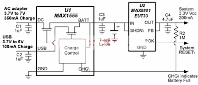
USB Charger Using IC MAX1555

This USB charger circuit is designed using the MAX1555 IC circuit manufactured by Maxim Semiconductor This MAX1555 USB charger can be used using the USB power or AC power.This MAX1555 charger is charging at 100mA from USB port and the maximum charging current increases to 350mA if the USB the AC adapter is connected . If both power types are connected in the same time the AC adapter is automatically given precedence. 

USB Charger Circuit diagram

MAX1555 USB Charger

This charger can be used for small devices like : PDAs ,Cell Phones , Digital Cameras , MP3 Players and other.The charger can be used for Li-Ion or Li-Polymer batteries . The electronic project charger circuit require a input voltage between 3V and 7 V and deliver an 3.3 V output voltage.As you can see in the circuit diagram , before the IC is connected the MAX8881 linear regulator IC which is capable to deliver up to 200mA.The MAX1881 is specially designed for battery-powered applications where reverse battery protection and long battery life are critical.
Read More..

Digital Clock Using with PIC16C54

Digital clock project based on the PIC16C54 microcontroller can be designed using the following circuit diagram . This digital clock electronic project based on the PIC16C54 is a simple time-of-day clock incorporating four seven-segment LED displays and three input switches. There is also an additional reset switch that would not normally be incorporated into the final design.

Digital clock Circuit diagram 


The common cathode for each display is turned on with transistors connected to the four I/O lines of PORTA . A low output turns on the PNP transistor for the selected display. The PORTB pins activate the LED segments.

The PORTB pins activate the LED segments. The switches are also connected to PORTB I/O pins.
When no buttons are pressed, the circuit will display the current time, starting at 12:00 on reset.
Pressing SW1 will cause seconds to be displayed. The time is set by pressing SW2 to advance minutes, and SW3 to advance hours . The displays used were common cathode and turned on with transistors to avoid trying to sink too much current into the PIC16C5X. 100 W resistors were used in series with the segments to obtain the desired brightness. Different values may be required if different displays are used.

All of the same display segments are linked together (A-A-A-A, B-B-B-B, etc.) and are individually selected by turning on only the desired display.
This simple digital clock project based on the PIC16C54 microcontroller must be powered from a simple 5 volt DC power supply circuit .
This digital clock project based on the PIC16C54 microcontroller ( circuit and software ) was designed by Dan Matthews Microchip Technology Inc . Download Source Code
Read More..

Sunday, December 8, 2013

Adjustable Power Supply 1 2 – 30V 5A using LM338


If you want to a variable dc voltage power supply circuit during 1.2V to 30Vdc and can provide a current maximum to 5A.

We may be have the many ways such as: to be modified the LM317 Variable Regulator 0-30V 1A by add the power transistor MJ2955 in circuit following Power supply regulator 1.2V-20V and 3V-6V-9V-12V 3Amp or will build the Variable dc regulator 0-30V 5A circuit to be well as well, But these methods. Rather cumbersome and wasting too money.

Adjustable Power Supply 1.2 – 30V 5A using LM338

However we can build this circuit easily and cheap, By using the packages IC No. LM338 only one, Similar to the LM317 IC number, but it can supply up to 5A, as the circuit shown in Fig.

How this circuit works
-The transformer T1 converts the AC 220V to 24 Vac, so be rectified the current by the bridge diode rectifier BD1 – 10A 400V. Until DCV has come out that the filter capacitor C1 is equal to 35 volt.
-The IC1 is the heart of the operation of this circuit. By the voltage output value obtained from the IC depends on the voltage value at the Adj pin of IC1, or can be varied by adjusting the VR1.
-However output voltage will be approximately equal to 1.25+1.25VR1/R1
The output voltage at the output pin of the IC1 is a more powerful filter with the capacitor C3.
Read More..

Thursday, December 5, 2013

Volume Controller Equalizer with using LM1036

This volume controller equalizer electronic project is designed using LM1036 DC tone volume controller with volume and balance circuit for stereo applications .An additional control input of the LM1036 allows loudness compensation to be simply effected.

Volume Controller Equalizer Circuit diagram


The four control inputs of the LM1036 volume controller provides control of the bass, treble, balance and volume functions through application of DC voltages from a remote control system or, alternatively, from four potentiometers which may be biased from a zenner regulated supply provided on the circuit.Each tone response is defined by a single capacitor chosen to give the desired characteristic.
Read More..

Friday, November 29, 2013

Smoke Detector Alarm Using RE46C140

Using the RE46C140 circuit can be designed a very simple smoke detector alarm using few external electronic components . The RE46C140 IC is a low power CMOS photoelectric type smoke detector IC that will provide all the required features for a photoelectric type smoke detector project . This smoke detector alarm design incorporates a gain selectable photo amplifier for use with an infrared emitter detector pair. An internal oscillator strobes power to the smoke detection circuitry for 100us every 10 seconds to keep standby current to a minimum. If smoke is sensed the detection rate is increased to verify an alarm condition.

Smoke Detector Alarm Circuit Diagram


An interconnect pin allows multiple detectors to be connected such that when one units alarms, all units will sound. In standby the LED is pulsed on for 10mS every 43 seconds . In a local alarm condition or the push to test alarm the LED pulse frequency is increased to once every 5 seconds. In the case of a remote alarm the LED not active. In the timer mode of operation the LED is pulsed on for 10mS every 10 seconds.

A comparator compares the photo amp output to an internal reference voltage. If the required number of consecutive smoke conditions is met the device will go into local alarm and the horn will be active. The bidirectional IO pin allows interconnection of multiple detectors. In a local alarm condition this pin is driven high immediately through a constant current source. Shorting this output to ground will not cause excessive current. The IO is ignored as an input during a local alarm. This smoke detector circuit must be powered from a 9 volt DC power supply .
Read More..