Showing posts with label detector. Show all posts

Friday, October 24, 2014

Invisible Broken Wire Detector

Invisible Broken Wire Detector Circuit diagram. Portable loads such as video cameras, halogen flood lights, electrical irons, hand drillers, grinders, and cutters are powered by connecting long 2- or 3-core cables to the mains plug. Due to prolonged usage, the power cord wires are subjected to mechanical strain and stress, which can lead to internal snapping of wires at any point. In such a case most people go for replacing the co e/cable, as finding the exact loca Portable loads such as video cameras, halogen flood lights, electrical irons, hand drillers, grinders, and cutters are powered by connecting long 2- or 3-core cables to the mains plug. Due to prolonged usage, the power cord wires are subjected to mechanical strain and stress, which can lead to internal snapping of wires at any point.

 In such a case most people go for replacing the core/cable, as finding the exact location of a broken wire is difficult. In 3-core cables, it appears almost impossible to detect a broken wire and the point of break without physically disturbing all the three wires that are concealed in a PVC jacket.  The circuit presented here can easily and quickly detect a broken/faulty wire and its breakage point in 1-core, 2-core, and 3-core cables without physically disturbing wires.  It is built using hex inverter CMOS CD4069. Gates N3 and N4 are used as a pulse generator that oscillates at around 1000 Hz in audio range.

The frequency is determined by timing components comprising resistors R3 and R4, and capacitor C1. Gates N1 and N2 are used to sense the presence of 230V AC field around the live wire and buffer weak AC voltage picked from the test probe. The voltage at output pin 10 of gate N2 can enable or inhibit the oscillator circuit. When the test probe is away from any high-voltage AC field, output pin 10 of gate N2 remains low. As a result, diode D3 conducts and inhibits the oscillator circuit from oscillating. Simultaneously, the output of gate N3 at pin 6 goes ‘low’ to cut off transistor T1. As a result, LED1 goes off. 

When the test probe is moved closer to 230V AC, 50Hz mains live wire, during every positive halfcycle, output pin 10 of gate N2 goes high. Thus during every positive half-cycle of the mains frequency, the oscillator circuit is allowed to oscillate at around 1 kHz, making red LED (LED1) to blink. (Due to the persistence of vision, the LED appears to be glowing continuously.) This type of blinking reduces consumption of the current from button cells used for power supply.  A 3V DC supply is sufficient for powering the whole circuit. AG13 or LR44 type button cells, which are also used inside laser pointers or in LED-based continuity testers, can be used for the circuit.
Invisible Broken Wire Detector Circuit diagram :

Invisible Broken Wire Detector Circuit diagram
Invisible Broken Wire Detector Circuit Diagram

The circuit consumes 3 mA during the sensing of AC mains voltage. For audio-visual indication, one may use a small buzzer (usually built inside quartz alarm time pieces) in parallel with one small (3mm) LCD in place of LED1 and resistor R5. In such a case, the current consumption of the circuit will be around 7 mA. Alternatively, one may use two 1.5V R6- or AA-type batteries. Using this gadget, one can also quickly detect fused small filament bulbs in serial loops powered by 230V AC mains. 

 The whole circuit can be accommodated in a small PVC pipe and used as a handy broken-wire detector. Before detecting broken faulty wires, take out any connected load and find out the faulty wire first by continuity method using any multimeter or continuity tester. 

Then connect 230V AC mains live wire at one end of the faulty wire, leaving the other end free. Connect neutral terminal of the mains AC to the remaining wires at one end. However, if any of the remaining wires is also found to be faulty, then both ends of these wires are connected to neutral. 

For single-wire testing, connecting neutral only to the live wire at one end is sufficient to detect the breakage point.  In this circuit, a 5cm (2-inch) long, thick, single-strand wire is used as the test probe. To detect the breakage point, turn on switch S1 and slowly move the test probe closer to the faulty wire, beginning with the input point of the live wire and proceeding towards its other end.LED1 starts glowing during the presence of AC voltage in faulty wire. When the breakage point is reached, LED1 immediately extinguishes due to the non-availability of mains AC voltage. The point where LED1 is turned off is the exact broken-wire point.  While testing a broken 3-core rounded cable wire, bend the probe’s edge in the form of ‘J’ to increase its sensitivity and move the bent edge of the test probe closer over the cable. During testing avoid any strong electric field close to the circuit to avoid false detection. 


Author :  K. Udhaya Kumaran Vu3gth - Copyright : EFY
Read More..

Monday, October 20, 2014

DTMF Proximity Detector

A DTMF-based IR transmitter and receiver pair can be used to realize a proximity detector. The circuit presented here enables you to detect any object capable of reflecting the IR beam and moving in front of the IR LED photo-detector pair up to a distance of about 12 cm from it. The circuit uses the commonly available telephony ICs such as dial-tone generator 91214B/91215B (IC1) and DTMF decoder CM8870 (IC2) in conjunction with infrared LED (IR LED1), photodiode D1, and other components as shown in the figure. A properly regulated 5V DC power supply is required for operation of the circuit.

The transmitter part is configured around dialer IC1. Its row 1 (pin 15) and column 1 (pin 12) get connected together via transistor T2 after a power-on delay (determined by capacitor C1 and resistors R1 and R16 in the base circuit of the transistor) to generate DTMF tone (combination of 697 Hz and 1209 Hz) corresponding to keypad digit “1” continuously. LED 2 is used to indicate the tone output from IC3. This tone output is amplified by Darlington transistor pair of T3 and T4 to drive IR LED1 via variable resistor VR1 in series with fixed 10-ohm resistor R14. Thus IR LED1 produces tone-modulated IR light.

DTMF Proximity Detector circuit diagramVariable resistor VR1 controls the emission level to vary the transmission range. LED 3 indicates that transmission is taking place. A part of modulated IR light signal transmitted by IR LED1, after reflection from an object, falls on photodetector diode D1. (The photodetector is to be shielded from direct IR light transmission path of IR LED1 by using any opaque partition so that it receives only the reflected IR light.) On detection of the signal by photodetector, it is coupled to DTMF decoder IC2 through emitter-follower transistor T1.

When the valid tone pair is detected by the decoder, its StD pin 15 (shorted to TOE pin 10) goes ‘high’. The detection of the object in proximity of IR transmitter-receiver combination is indicated by LED1. The active-high logic output pulse (terminated at connector CON1, in the figure) can be used to switch on/off any device (such as a siren via a latch and relay driver) or it can be used to clock a counter, etc. This DTMF proximity detector finds applications in burglar alarms, object counter and tachometers, etc.
Read More..

Thursday, September 18, 2014

Snail Mail Detector

Since his letter-box is outdoors  and quite some way from the  house, the author was looking  for a simple means of knowing if  the postman had been without  having to go outside (contrary  to popular belief, the weather  isn’t always fine in the South of  France). Circuits for this kind of  ‘remote detection’ come up regularly, but always involve running cables between the letter- box and the detection circuit in  the house. Seeking to avoid running any extra cables, the author  had the idea of using the existing cables going to the doorbell,  conveniently located adjacent to  his letter-box.
 Snail Mail Detector1
The letter-box has two doors:  one  on  the  street  side  for  the  postman, and one on the gar-den side for collecting the post.  A  micro switch  is  fitted  to  the  street-side door, to light an indicator in the house showing that  the postman has been. A second  micro switch is fitted to the door  on the garden side, to turn off  the indicator once the post has  been collected. The only difficulty then remains to connect  these detectors to a remote circuit in the house that remembers  whether  the  postman’s  been or not.
Snail Mail Detector2
 
The idea was to use the alternating half-cycles of the AC signal  on the cable going to the door-bell  to  transmit  the  information, according to the following logic:
  • Both  half-cycles  present: no change in the status of the mail detector.
  • An interruption (even brief) of one half-cycle: indicator lights permanently.
  • An interruption (even brief) of the other half-cycle: the indicator goes out.
Note that the signal is tapped off  across the doorbell coil via R6  and the pair of diodes connected  in inverse-parallel (to limit the  signal,  par ticularly  when  the  bell is rung). The signal is then  filtered by R2/C1, before being  used by IC1, which is wired as a  comparator with hysteresis. The  trigger threshold is adjusted by  P1, using a pair of inverse parallel diodes as a voltage reference  (positive or negative according  to the output state):
 
For the detection to work, there  has to be continuity in the bell-push circuit this is generally  ensured by the little lamp illuminating the bell-push. Resistor R1  is added just in case the lamp is  blown or not present. To keep things simple, the circuit is powered directly from the  doorbell transformer itself (230 V  / 8 V). The author managed to fit  the little circuit within the door-bell unit, with the LED poking  through a hole in the casing so  it is readily visible in the hall of  his house. 

Author : Philippe Temporelli (France) – Copyright : elektor electronics
Read More..

Wednesday, February 5, 2014

Smoke detector circuit

This causes the resistance of LDR to increase and the voltage at the base of the transistor is pulled high due to which the supply to the COB (chip-on-board) is completed. The sensitivity of the smoke detector depends on the distance between bulb and LDR as well as setting of preset VR1.
Thus by placing the bulb and the LDR at appropriate distances, one may vary preset VR1 to get optimum sensitivity.
We have not build this smoke alarm detector.

For smoke detector installation and maintenance use a near electrician.
Read More..

Tuesday, January 28, 2014

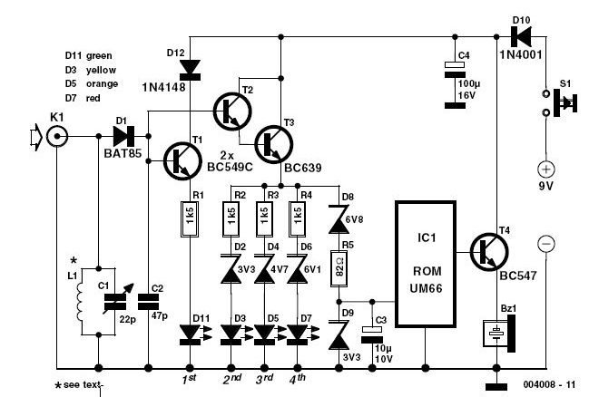
144 MHz Simple RF Detector Circuit

144 MHz Simple RF Detector Circuit
This simple circuit helps you sniff out RF radiation from your transmitter, improper joints, a broken wire or poor equipment with RF shielding. The tester is designed for the radio band amateur 2 meter (144-146 MHz in Europe). The instrument has a reading of 4-step LED and an audible alarm for high voltage radiation. The RF signal is received by an antenna and made to resonate by C1-L1. After rectification by the diode D1, the signal is fed to a two transistor Darlington amplifier HighGain, T2-T3. Assuming a 10-inch telescoping antenna using the RF level scale established for the LEDs is as follows:

When all the LEDs light, the (optional) UM66 sound / melody generator chip (IC1) also operates and provides an audible alarm. By changing the zener diode values ​​of D2, D4, D6 and D8, the step size and duration of the instrument may change as needed. To operate in other bands of ham or PMR, simply change the network-L1 C1 resonance.

For example, a transceiver 5 watt handheld equipped with a telescoping half-wave antenna (G = 3.5 dBd), there is an ERP (Effective Radiated Power) of just 10 watts and an emf of more than 8 volts near the head. Inductor L1 consists of 2.5 turns of 20 SWG (approximately 1 mm in diameter) enameled copper wire. The inner diameter is approximately 7 mm and no core is used.

Trimmer capacitor C1 associates is adjusted for the greatest number of LEDs to light at a relatively low fieldstrength position for a 2 m transceiver 145 MHz transmission. The tester is powered by a 9 V battery and consumes about 15 mA when all LEDs are on. Must be enclosed in a metal box.
Read More..

Sunday, January 12, 2014

Photo Transistor Detector


All of the circuits on the PCB are configured so with the intention of as the photosensors are dark, the output of the 556 timers want stay peak. The issue delay period of each one 556 timer can be tainted by selecting as it should be combination ideals representing the R7/C2, R8/C3, R9/C4 and R10/C5 pairs.The LM339 input detection voltage levels for the circuit while publicized is settle on on 1/2 of the supply voltage. If a subordinate before elevated detection level voltage is wanted, the standards of resistors R5 and R6 can be there misused to suit.hint as soon as power is functional to the circuit, the outputs of the 556 timers pray be piercing in place of 1 discharge delay period phase. (Until the timing capacitors hold charged to 2/3rds of the supply voltage.) in attendance are RESET inputs for apiece LM556. 

Photo Transistor Detector
These inputs complete not have terminal stop contacts but do have pads with holes to solder wires to if considered necessary. The RESET inputs might take place used to force the outputs of the 556 timers LOW until the timing capacitors have fully charged behind power is practical to the circuit but an outer timer would be required to accomplish this.This circuit does not require a regulated power supply and can carry on on supply voltages of up to 15 volts.

on behalf of in turn on other light detector circuits, comprehend Light Activated Detector Circuits by the side of this put.For added broad in a row on Voltage Comparators see the Voltage Comparator in sequence piece of paper by the side of this place.on behalf of further universal in sequence on LM556 timers see the 555 Timer Information bleep next to this place.threatening - If the polarity of the power supply for this circuit is reversed before the circuit is connected to an AC or else DCC source this circuit pray exist damaged. The most supply voltage meant for this circuit is 15 Volts.
Read More..

Saturday, December 7, 2013

Glitch Detector Schematic

In the circuit, two op amps (half of an LM324 quad op amp) and an SCR are direct coupled in a de-voltage monitoring circuit. Op-amp U1-a is configured as a voltage follower, which feeds the bridged inputs of the second op amp, Ul-b. A resistor/capacitor combination (R2/C1) connected to the negative input of U1-b forms an RC time-delay circuit.

Glitch Detector Circuit Schematic


As long as there is no change in the de-voltage level at either of U1-bs inputs, its output is near zero. If a voltage glitch occurs, the RC timing circuit will delay the voltage change at the op amps inverting input, causing its output to go high, triggering SCR1 and causing LED1 to light. The circuits sensitivity allows it to detect voltage changes in the millivolt range. Pressing S1 diverts the SCRs holding current to ground, causing it to turn off and reset the circuit.
Read More..

Friday, November 29, 2013

Smoke Detector Alarm Using RE46C140

Using the RE46C140 circuit can be designed a very simple smoke detector alarm using few external electronic components . The RE46C140 IC is a low power CMOS photoelectric type smoke detector IC that will provide all the required features for a photoelectric type smoke detector project . This smoke detector alarm design incorporates a gain selectable photo amplifier for use with an infrared emitter detector pair. An internal oscillator strobes power to the smoke detection circuitry for 100us every 10 seconds to keep standby current to a minimum. If smoke is sensed the detection rate is increased to verify an alarm condition.

Smoke Detector Alarm Circuit Diagram


An interconnect pin allows multiple detectors to be connected such that when one units alarms, all units will sound. In standby the LED is pulsed on for 10mS every 43 seconds . In a local alarm condition or the push to test alarm the LED pulse frequency is increased to once every 5 seconds. In the case of a remote alarm the LED not active. In the timer mode of operation the LED is pulsed on for 10mS every 10 seconds.

A comparator compares the photo amp output to an internal reference voltage. If the required number of consecutive smoke conditions is met the device will go into local alarm and the horn will be active. The bidirectional IO pin allows interconnection of multiple detectors. In a local alarm condition this pin is driven high immediately through a constant current source. Shorting this output to ground will not cause excessive current. The IO is ignored as an input during a local alarm. This smoke detector circuit must be powered from a 9 volt DC power supply .
Read More..