Showing posts with label rf. Show all posts
Showing posts with label rf. Show all posts
Tuesday, February 4, 2014
Diagram Basic RF Oscillator

This basic circuit is simple to create and the tools are not critical . Most of them can be found in your junk parts box .
The L1 antenna coil can be made by close winding 8 to 10 turns of 22 gauge insulated hookup wire around a
1/4 inch form such as a pencil .
You can exeprement with the size of the copile and the number of turns to see how it affects the frequency and singnal out put of the oscilatter .
You ought be able to pick up its signal with a standard FM radio receiver . The signal in ought be coupled by a disc capacitor of about 0.1 uF to stage in main of it .
Author
Saifullah soomro

Tuesday, January 28, 2014
144 MHz Simple RF Detector Circuit
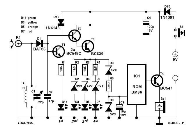
This simple circuit helps you sniff out RF radiation from your transmitter, improper joints, a broken wire or poor equipment with RF shielding. The tester is designed for the radio band amateur 2 meter (144-146 MHz in Europe). The instrument has a reading of 4-step LED and an audible alarm for high voltage radiation. The RF signal is received by an antenna and made to resonate by C1-L1. After rectification by the diode D1, the signal is fed to a two transistor Darlington amplifier HighGain, T2-T3. Assuming a 10-inch telescoping antenna using the RF level scale established for the LEDs is as follows:
When all the LEDs light, the (optional) UM66 sound / melody generator chip (IC1) also operates and provides an audible alarm. By changing the zener diode values of D2, D4, D6 and D8, the step size and duration of the instrument may change as needed. To operate in other bands of ham or PMR, simply change the network-L1 C1 resonance.
For example, a transceiver 5 watt handheld equipped with a telescoping half-wave antenna (G = 3.5 dBd), there is an ERP (Effective Radiated Power) of just 10 watts and an emf of more than 8 volts near the head. Inductor L1 consists of 2.5 turns of 20 SWG (approximately 1 mm in diameter) enameled copper wire. The inner diameter is approximately 7 mm and no core is used.
Trimmer capacitor C1 associates is adjusted for the greatest number of LEDs to light at a relatively low fieldstrength position for a 2 m transceiver 145 MHz transmission. The tester is powered by a 9 V battery and consumes about 15 mA when all LEDs are on. Must be enclosed in a metal box.
When all the LEDs light, the (optional) UM66 sound / melody generator chip (IC1) also operates and provides an audible alarm. By changing the zener diode values of D2, D4, D6 and D8, the step size and duration of the instrument may change as needed. To operate in other bands of ham or PMR, simply change the network-L1 C1 resonance.
For example, a transceiver 5 watt handheld equipped with a telescoping half-wave antenna (G = 3.5 dBd), there is an ERP (Effective Radiated Power) of just 10 watts and an emf of more than 8 volts near the head. Inductor L1 consists of 2.5 turns of 20 SWG (approximately 1 mm in diameter) enameled copper wire. The inner diameter is approximately 7 mm and no core is used.
Trimmer capacitor C1 associates is adjusted for the greatest number of LEDs to light at a relatively low fieldstrength position for a 2 m transceiver 145 MHz transmission. The tester is powered by a 9 V battery and consumes about 15 mA when all LEDs are on. Must be enclosed in a metal box.
Subscribe to:
Posts (Atom)