Showing posts with label simple. Show all posts

Friday, October 24, 2014

Simple Water Level Indicator Circuit Schematic

The whole project was developed on a friends request. Its purpose was to remotely monitor the water-level in a metal tank located in the attic by means of a very simple control unit placed in the kitchen, some floors below.
Mains requirements were:
  1. No separate supply for the remote circuit
  2. Main and remote units connected by a thin two-wire cable
  3. Simple LED display for the main unit
  4. Battery operation to avoid problems related to mains supply and water proximity
  5. As the circuit was battery operated a low current consumption was obviously welcomed
The very small remote unit is placed near the tank and measures the water level in three ranges by means of two steel rods. Each range will cover one third of the tank capacity:

Almost empty - signaled by means of a red LED (D3) in the control unit display
About half-level - signaled by means of a yellow LED (D2) in the control unit display
Almost full - signaled by means of a green LED (D1) in the control unit display

Circuit diagram:

Water-level Indicator Circuit Diagram

Circuit operation:

When the water-level is below the steel rods, no contact is occurring from the metal can and the rods, which are supported by a small insulated (wooden) board. The small circuit built around IC1 draws no current and therefore no voltage drop is generated across R5. IC2A, IC2B and Q1 are wired as a window comparator and, as there is zero voltage at input pins #2 and #5, D3 will illuminate. When the water comes in contact with the first rod, pin #13 of IC1 will go high, as its input pins #9 to #12 were shorted to negative by means of the water contact.

Therefore, R4 will be connected across the full supply voltage and the remote circuit will draw a current of about 9mA. This current will cause a voltage drop of about 0.9V across R5 and the window comparator will detect this voltage and will change its state, switching off D3 and illuminating D2. When the water will reach the second rod, also pin #1 of IC1 will go high for the same reason explained above. Now either R3 and R4 will be connected across the full supply voltage and the total current drawing of the remote circuit will be about 18mA.

The voltage drop across R5 will be now about 1.8V and the window comparator will switch off D2 and will drive D1. The battery will last very long because the circuit will be mostly in the off state. Current is needed only for a few seconds when P1 is pushed to check the water-level and one of the LEDs illuminates.

Parts:

R1 = 15K 1/4W Resistors
R2 = 15K 1/4W Resistors
R3 = 1K 1/4W Resistors
R4 = 1K 1/4W Resistors
R5 = 100R 1/4W Resistor
R6 = 47K 1/4W Resistor
R7 = 3.3K 1/4W Resistors
R8 = 3.3K 1/4W Resistors
R9 = 2.7K 1/4W Resistors
R10 = 15K 1/4W Resistors
R12 = 15K 1/4W Resistors
R13 = 3.3K 1/4W Resistors
R14 = 2.7K 1/4W Resistors
R15 = 2.7K 1/4W Resistors
D1 = 3mm Green LED
D2 = 3mm Yellow LED
D3 = 3mm Red LED
C1 = 470nF 63V Polyester or Ceramic Capacitor
J1 = Two ways output sockets
J2 = Two ways output sockets
P1 = SPST pushbutton
B1 = 9V PP3 Battery
Q1 = BC547 45V 100mA NPN Transistor
IC1 = 4012 Dual 4 input NAND gate IC
IC2 = LM393 Dual Comparator IC
Two steel rods of appropriate length
Read More..

Simple Clock pulse Generator with CD4049

If you want to generate clock with CD4049 CMOS you can do as the follow picture.The typical resister values is 100K and Capacitor is 0.01-0.1uF.The output frequency is about 1/1.1RC ___Hz

Read More..

Simple Voltage to Frequency Converter Circuits Diagram

This Simple Voltage to Frequency Converter Circuits Diagram has a 1 Hz-to-30 MHz output, 150-dB dynamic range, for a 0 to 5 V input. It maintains 0.08% linearity over its entire 71/3 decade range with a full-scale drift of about 20 ppm/°C. To get the additional bandwidth, the fast )FET buffer drives the Schottky TTL Schmitt trigger. 

Simple Voltage to Frequency Converter Circuits Diagram

Simple Voltage to Frequency Converter Circuits Diagram

The Schottky diode prevents the Schmitt trigger from ever seeing negative voltage at its input. The Schmitt`s input voltage hysteresis provides the limits which the oscillator runs between. The 30-MHz, full-scale output is much faster than the LTC1043 can accept, so the digital divider stages are used to reduce the feedback frequency signal by a factor of 20. The remaining Schmitt sections furnish complementary outputs.
Read More..

Simple Tremolo Effect

This tremolo effect circuit uses the XR2206 and the TCA730 IC which is designed as an electronic balance and volume regulator with frequency correction. The circuit is use full for stereo channels and it also has the ability to simulate the Lesley effect aka rotating loudspeaker effect.

 How does the tremolo effect circuit works
Balance and volume settings are done with a linear potentiometer for both channels. If this potentiometer is replaced with an AC voltage source, a periodic modulation of the input signal can be achieved. This AC voltage source comes from the function generator IC XR2206. This IC generates square, triangle and sine wave signals but for this project we use only the sine wave.

IC Tremolo effect circuit schematic

Circuit Project: DIY Tremolo Effect Circuit
The modulation voltage can be varied with P1 from 1 Hz up to 25 Hz. Resistor R3 sets the operation level of the sine wave generator. R5 and R6 set the DC voltage and the sine wave amplitude at the output. C2 is a ripple filter. The square wave output of the XR2206 drives T2 and a LED to optically display the frequency.

The modulating voltage reaches pin 13 of TCA730 via P3 and R10. This input functions as the volume control or in this case the volume modulation. The degree of the balance modulation (Lesley effect) can be varied with P2. A regulated power supply using 7815 IC is recommended. Do not use a non-stabilized power supply since the current variations would influence the modulation negatively.
Attach the 7815 IC to a good heat sink (about 10 cm2).
Read More..

Monday, October 20, 2014

Simple Mat Switch Circuit

This simple Simple Mat Switch Circuit Diagram produces a warning beep when somebody crosses a protected area in your home or office. The switch, hidden be-low the floor mat, triggers the alarm when the person walks over it.

The circuit uses a conductive foam as the switch. It can be two small pieces of conductive pads usually used to pack sensitive ICs as antistatic cover. Alternatively, you can make the switch by coating conducting carbon ink on two small pieces of a copper-clad board.

Circuit diagram :

Link


Simple Mat Switch Circuit Diagram

When the circuit is in standby mode, transistor T1 does not conduct, since its base is floating. When the person walks, the switch is pressed and current flows through R1 and the switch to provide positive bias to transistor T1. Transistor T1 conducts and its collector voltage drops, which acts as a negative trigger input for the monostable wired around IC NE555 (IC1).

IC1 outputs a pulse of fifty-seconds duration with preset values of R4 and C3. This pulse is applied to the buzzer through transistor T2. The buzzer sounds a warning beep on unauthorised entry. The pulse duration can be changed to the desired value by changing the values of R4 and C3. Resistor R2 in the circuit makes the trigger pin of IC1 high to prevent false triggering.

Assemble the circuit on a general-purpose PCB and enclose in a plastic case. Use a 9V battery to power the circuit. Connect the touchpad switch with the PCB and hide under the mat at the entrance. The PCB can be mounted on the nearby wall.

Make the switch carefully using conducting foam or copper clad coated with conducting ink. Place the two pieces with their conducting surface facing each other. Solder carefully a thin copper electric wire and ensure that it makes contact when the two plates touch together on pressing. Provide two 1cm rubber tabs between the plates to avoid touch in the standby mode.
Read More..

Simple Solar Engine Circuit Diagram

 Simple Solar Engine Circuit Diagram
 
Simple Solar Engine Circuit Diagram Small DC motor runs off of calculator solar cell in dim light. How do we achive 10nA operation? By using diodes in place of pull up resistors, and by isolating the DC load from the trigger circuit via junction drops and the 10nF capacitor. If there is too much power comming from the solar cell then the motor might run too often or even continuously. You can avoid this by putting a 100K ohm resistor in series with the solar cell. 

 Simple Solar Engine Circuit Diagram

 Simple Solar Engine Circuit Diagram

Read More..

Friday, October 17, 2014

Build a Simple Audio Amplifier 2800W Circuit Diagram

How to Build a Simple Audio Amplifier 2800W Circuit Diagram. This is a Mono high power amplifier is actually a powerful 1400 W, but if this high power amplifier circuit is doubled and you want to create stereo, high power amplifier the necessary components and pcb requires two-fold. So if the stereo high power amplifier 2 X 1400W. Schematic Circuit diagram is still less by looking at the circuit that was so below, the finished circuit has been added with a gains using JRC4558 IC by the two and the picture ic where it can be seen below. 

For circuit buffers, drivers, and booster use multiple transistors and other components (can be seen listed component). And high power amplifier project that is so below is just part of the buffer and driver while the booster has not been made​​. For additional transistors in the booster or high power amplifier end scheme can be found Booster output power amplifier.

 Audio Amplifier 2800W Circuit Diagram


Part List :

Resistor
R1_____560Ω
R2_____100Ω
R3_____2K2Ω
R4_____560Ω
R5_____1Ω
R6_____27KΩ
R7_____10KΩ
R8_____100Ω
R9_____100Ω
R10____100Ω
R11____12KΩ
R12____100Ω
R13____100Ω
R14____100Ω
R15____27KΩ
R16____2K2Ω
R17____560Ω
R18____100Ω
R19____10KΩ
R20____330Ω
R21____47Ω 2W
R22____56Ω
R23____2K2Ω
R24____22Ω
R25____56Ω
R26____180Ω
R27____500-1KΩ Trim
R28____560Ω
R29____56Ω
R30____56Ω
R31____22Ω 1W
R32____5Ω6 2W
R33____10Ω
R34____180Ω
R35____100Ω
R36____22Ω 2W
R37____180Ω
R38____56Ω
R39____47Ω 2W
R40____5Ω6 2W
R41____10Ω
R42____10Ω
R43____10Ω
R45____10Ω
R46____0.22Ω 5W
R47____0.22Ω 5W
R48____0.22Ω 5W
R49____0.22Ω 5W
R50____10Ω 5W

Capacitor
C1_____1цF
C2_____1.5nF
C3_____0.1цF 250-275V
C4_____0.1цF 250-275VC5_____100nF
C6_____100цF 50V
C7_____39pF
C8_____330pF
C9_____330pF
C10____330pF
C11____47nF 250-275V
C12____220nF 250-275V

Transistor
T1_____MJE340
T2_____2N5551 / C2240
T3_____2N5551 / C2240
T4_____2N5551 / C2240
T5_____2N5551 / C2240
T6_____2N5401 / BF423
T7_____2N5401 / BF423
T8_____2N5401 / BF423
T9_____2N5401 / BF423
T10____MJE350
T11____B1186
T12____TIP127
T13____D1763
T14____D1763
T15____B1186
T16____C5198
T17____A1941
T18____2SC2922 / MJ15024G
T19____2SC2922 / MJ15024G
T20____2SA1216 / MJ15025G
T21____2SA1216 / MJ15025G


Sourced by SIGMA-4 Madiun ©
Read More..

Thursday, September 18, 2014

A Simple Function Generator

Simple triangle-wave generators have a weakness in that the waveform of their output signal normally cannot be modified. The circuit presented here makes it possible to smoothly alter the waveform of a linearly rising and steeply trailing saw-tooth signal through a symmetrical triangle-wave to a slowly trailing, steeply rising linear sawtooth. The wanted waveform may be selected independently of the frequency, which can also be varied uniformly from 0.2 Hz to 8 kHz. At the same time, a rectangular signal with variable duty cycle (also independent of frequency) is available at the rectangular-signal output of the circuit.

Simple_Function_Generator_Circuit_Diagram1 
The circuit consists of integrator IC1b, whose output is applied to comparator IC1c. The output of the comparator is a rectangular signal The output of IC1b is raised by amplifier IC1d to a level that allows the full output voltage range of the operational amplifier to be used. Op amp IC1a provides a stable virtual earth, whose level is set to half the supply voltage with P1. The smooth setting of the frequency is made possible by feedback of part of the output of the comparator to the input of the integrator via P2. This preset is usually not provided in standard triangle-wave generators. Network D1-R1-D2-R2-P3 makes it possible to give integrator capacitor C3 different charging and discharge times.

This arrangement enables the output signal at A1 and the duty cycle of the rectangular wave signal at A2 to be varied. Varying the amplification factor with P5 has no effect on the frequency set with P2. The slope of the signal edges, the transient responses, and the output voltage range (rail-to-rail or with some voltage drop) depend on the type of op amp used. The TL084 used in the prototype offers a good compromise between price and meeting the wanted parameters. The circuit is best built on a small piece of prototyping board. The circuit draws a current of not more than 12 mA.

Brief parameters:
Provides triangle-wave, sawtooth or rectangular signal
Waveform variable independently of frequency (triangle wave and sawtooth)
Duty cycle of rectangular signal can be set independently of frequency
Applications:
Test and measurement
Pulse-width control
Summary of preset action:
P1 – sets virtual earth to a level equal to Ucc/2;
P2 – sets the frequency;
P3– sets the waveform;
P4 – sets the hysteresis of the comparator (frequency and amplitude of the triangle-wave signal)
P5 – sets the amplification of the triangle-wave and sawtooth signals.


www.ecircuitslab.com
Read More..

Friday, February 7, 2014

Simple Oscillator Pipe Locator

Sometimes the need arises to construct a really simple oscillator. This could hardly be simpler than the circuit shown here, which uses just three components, and offers five separate octaves, beginning around Middle C (Stage 14). Octave # 5 is missing, due to the famous (or infamous) missing Stage 11 of the 4060B IC. We might call this a Colpitts ‘L’ oscillator, without the ‘C’. Due to the reactance of the 100-µH inductor and the propagation delay of the internal oscillator, oscillation is set up around 5 MHz. When this is divided down, Stage 14 approaches the frequency of Middle C (Middle C = 261.626 Hz).


Stages 13, 12, 10, and 9 provide higher octaves, with Stages 8 to 4 being in the region of ultrasound. If the oscillator’s output is taken to the aerial of a Medium Wave Radio, L1 may serve as the search coil of a Pipe Locator, with a range of about 50 mm. This is tuned by finding a suitable heterodyne (beat note) on the medium wave band. In that case, piezo sounder Bz1 is omitted. The Simple Oscillator / Pipe Locator draws around 7mA from a 9-12 V DC source.
Read More..

Wednesday, February 5, 2014

Simple Acoustic Sensor

This acoustic sensor was originally developed for an industrial application (monitoring a siren), but will also find many domestic applications. Note that the sensor is designed with safety of operation as the top priority: this means that if it fails then in the worst-case scenario it will not itself generate a false indication that a sound is detected. Also, the sensor connections are protected against polarity reversal and short-circuits. The supply voltage of 24 V is suitable for industrial use, and the output of the sensor swings over the supply voltage range.
Circuit diagram :
simple Acoustic Sensor-Circuit Diagram
Simple Acoustic Sensor Circuit Diagram
The circuit consists of an electret micro-phone, an amplifier, attenuator, rectifier and a switching stage. MIC1 is supplied with a current of 1 mA by R9. T1 amplifies the signal, decoupled from the supply by C1, to about 1 Vpp. R7 sets the collector current of T1 to a maximum of 0.5 mA. The operating point is set by feedback resistor R8. The sensitivity of the circuit can be adjusted using potentiometer P1 so that it does not respond to ambient noise levels. Diodes D1 and D2 recitfy the signal and C4 provides smoothing. As soon as the voltage across C4 rises above 0.5 V, T2 turns on and the LED connected to the collector of the transistor lights. T3 inverts this signal.
If the microphone receives no sound, T3 turns on and the output will be at ground. If a signal is detected, T3 turns off and the output is pulled to +24 V by R4 and R5. In order to allow for an output current of 10 mA, T3’s collector resistor needs to be 2.4 kΩ. If 0.25 W resistors are to be used, then to be on the safe side this should be made up of two 4.7 kΩ resistors wired in parallel. Diode D4 protects the circuit from reverse polarity connection, and D3 protects the output from damage if it is inadvertently connected to the supply. 

Read More..

Tuesday, January 28, 2014

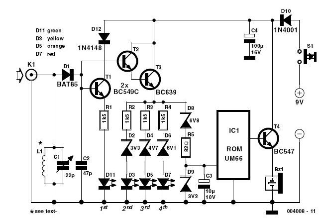
144 MHz Simple RF Detector Circuit

144 MHz Simple RF Detector Circuit
This simple circuit helps you sniff out RF radiation from your transmitter, improper joints, a broken wire or poor equipment with RF shielding. The tester is designed for the radio band amateur 2 meter (144-146 MHz in Europe). The instrument has a reading of 4-step LED and an audible alarm for high voltage radiation. The RF signal is received by an antenna and made to resonate by C1-L1. After rectification by the diode D1, the signal is fed to a two transistor Darlington amplifier HighGain, T2-T3. Assuming a 10-inch telescoping antenna using the RF level scale established for the LEDs is as follows:

When all the LEDs light, the (optional) UM66 sound / melody generator chip (IC1) also operates and provides an audible alarm. By changing the zener diode values ​​of D2, D4, D6 and D8, the step size and duration of the instrument may change as needed. To operate in other bands of ham or PMR, simply change the network-L1 C1 resonance.

For example, a transceiver 5 watt handheld equipped with a telescoping half-wave antenna (G = 3.5 dBd), there is an ERP (Effective Radiated Power) of just 10 watts and an emf of more than 8 volts near the head. Inductor L1 consists of 2.5 turns of 20 SWG (approximately 1 mm in diameter) enameled copper wire. The inner diameter is approximately 7 mm and no core is used.

Trimmer capacitor C1 associates is adjusted for the greatest number of LEDs to light at a relatively low fieldstrength position for a 2 m transceiver 145 MHz transmission. The tester is powered by a 9 V battery and consumes about 15 mA when all LEDs are on. Must be enclosed in a metal box.
Read More..

Thursday, January 9, 2014

Simple 6V charger battery circuit

This is very simple charger 9V - 30V battery charger with main operation by IC LM317L and 2N222 transistor. Direct input DC voltage , the recomended capacitor is 1000uf. It can be filtering Output voltage and make long-lasting battery. And easy to make this circuit , without using the PCB would be able to.
See the Charger Schematic and troubleshooting below :
If it cant working , then the mistakes and keeping the following :
  • Check input voltage, whether working or not.
  • Check the installation of the pins of components.
  • Chek transistor , at input voltage , base , and output voltage.
  • Check IC input voltage and output voltage , there or not.

Thank  you 4 visiting my blog.
Read More..

Sunday, December 22, 2013

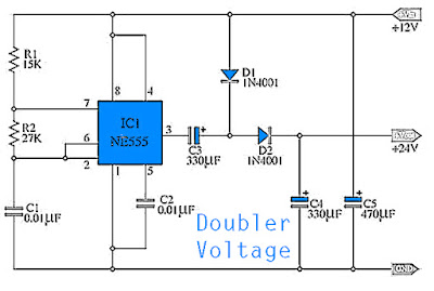
Simple Doubler Voltage 12 to 24Volt DC

This take place simple Doubler Voltage circuit, from voltage 12VDC to be 24VDC. By benefit Timer IC highly prevalent the come to NE555 and other equipment a modest again. It can make happen current contract in relation to 50mA fitting pro the circuit, with the intention of use low current the insignificant-sized.

Simple Doubler Voltage 12 to 24 VDC Circuit
Simple Doubler Voltage 12 to 24 VDC Schematic Diagram
The belief facility of the circuit be present, at what time use Volt input 12VDC give with the circuit long for converge Filter current smoothly with increasingly. The capacitors C5 give with IC1, The resistor R1,R2 and , capacitors C1, Which build the circuit ideal astable multi vibrator open place wave generator, by the side of the frequency with reference to 2KHz befall shown the way pin 3 of IC1. By take capacitors C3,C4 diode D1 and D2. Which build come to pass boost up voltage x 2,which self-control enhance the level Volt out be the sincere current about 24VDC or else 2 time of the level Volt input.

Read More..

Friday, November 29, 2013

Simple accu charger circuit

charger schematics
Accu charger circuit is very simple and easy to make, because it only requires a few components are also not more than 10 components. Besides easy charger circuit is also very cheap and very efficient. 


This circuit requires power supply from a transformer that comes from an AC voltage 220 ​​and diuturunkan be 12-13 volts and then enter to-circuit and 12 Volt DC output allows for charging 12V ​​battery

charger schematics circuit
Simple charger schematics
Read More..

Thursday, November 21, 2013

Simple Circuit 12V to 120V DC DC Converter

Simple Circuit 12V to 120V DC DC ConverterIts a simple circuit of 12V DC to 120V DC converter. The circuit consists of two phases first phase of the investor base and then a rectifier and filter stage. IC1 NE555 is wired as an astable multivibrator operating at a frequency of 100 Hz and can be adjusted to the preset R1. IC1 output is coupled to the clock input of IC2 is a dual CMOS D flip-flop. IC2 divides the pulse train of 100 Hz IC1 2 50 Hz pulse trains that are 180 degrees out of the party and offered on the pin 1 and 2 of IC2.


When pin 1 is high transistor Q1 conducts and current flows through the upper half of T1 primary winding. When pin 2 is the transistor Q2 conducts and high current flows through the lower half of the primary coil T1. As a result of a voltage of 120 V AC are induced in the secondary of T1. This voltage is rectified with bridge D1 to provide a 120V DC output. Capacitor C2 is the DC input filter, while C3, C4 are the output filters.


Notes.
  • The circuit can be assembled on a vero board.
  • Q1 and Q2 require heat sink.
  • Output power of this dc dc converter is around 100 watts.
  • IC1 and IC2 are to be mounted on holders.
  • An optional 5A fuse can be added in series to the 12V supply line.
  • T1 can be a 9-0-9V /250V/3A mains transformer.
  • If 3A bridge is not available make one using 1N5408 diodes.
  • Out of the two Flip-Flops inside CD4013 only one is used here.
  • Output of IC1 must be set to 100Hz by adjusting preset R1
Read More..