Showing posts with label indicator. Show all posts

Friday, October 24, 2014

Simple Water Level Indicator Circuit Schematic

The whole project was developed on a friends request. Its purpose was to remotely monitor the water-level in a metal tank located in the attic by means of a very simple control unit placed in the kitchen, some floors below.
Mains requirements were:
  1. No separate supply for the remote circuit
  2. Main and remote units connected by a thin two-wire cable
  3. Simple LED display for the main unit
  4. Battery operation to avoid problems related to mains supply and water proximity
  5. As the circuit was battery operated a low current consumption was obviously welcomed
The very small remote unit is placed near the tank and measures the water level in three ranges by means of two steel rods. Each range will cover one third of the tank capacity:

Almost empty - signaled by means of a red LED (D3) in the control unit display
About half-level - signaled by means of a yellow LED (D2) in the control unit display
Almost full - signaled by means of a green LED (D1) in the control unit display

Circuit diagram:

Water-level Indicator Circuit Diagram

Circuit operation:

When the water-level is below the steel rods, no contact is occurring from the metal can and the rods, which are supported by a small insulated (wooden) board. The small circuit built around IC1 draws no current and therefore no voltage drop is generated across R5. IC2A, IC2B and Q1 are wired as a window comparator and, as there is zero voltage at input pins #2 and #5, D3 will illuminate. When the water comes in contact with the first rod, pin #13 of IC1 will go high, as its input pins #9 to #12 were shorted to negative by means of the water contact.

Therefore, R4 will be connected across the full supply voltage and the remote circuit will draw a current of about 9mA. This current will cause a voltage drop of about 0.9V across R5 and the window comparator will detect this voltage and will change its state, switching off D3 and illuminating D2. When the water will reach the second rod, also pin #1 of IC1 will go high for the same reason explained above. Now either R3 and R4 will be connected across the full supply voltage and the total current drawing of the remote circuit will be about 18mA.

The voltage drop across R5 will be now about 1.8V and the window comparator will switch off D2 and will drive D1. The battery will last very long because the circuit will be mostly in the off state. Current is needed only for a few seconds when P1 is pushed to check the water-level and one of the LEDs illuminates.

Parts:

R1 = 15K 1/4W Resistors
R2 = 15K 1/4W Resistors
R3 = 1K 1/4W Resistors
R4 = 1K 1/4W Resistors
R5 = 100R 1/4W Resistor
R6 = 47K 1/4W Resistor
R7 = 3.3K 1/4W Resistors
R8 = 3.3K 1/4W Resistors
R9 = 2.7K 1/4W Resistors
R10 = 15K 1/4W Resistors
R12 = 15K 1/4W Resistors
R13 = 3.3K 1/4W Resistors
R14 = 2.7K 1/4W Resistors
R15 = 2.7K 1/4W Resistors
D1 = 3mm Green LED
D2 = 3mm Yellow LED
D3 = 3mm Red LED
C1 = 470nF 63V Polyester or Ceramic Capacitor
J1 = Two ways output sockets
J2 = Two ways output sockets
P1 = SPST pushbutton
B1 = 9V PP3 Battery
Q1 = BC547 45V 100mA NPN Transistor
IC1 = 4012 Dual 4 input NAND gate IC
IC2 = LM393 Dual Comparator IC
Two steel rods of appropriate length
Read More..

Flat Battery Indicator

This small circuit was developed to monitor the battery in a model hovercraft. The lift in the model is produced by an electric motor driving a fan. To avoid the possibility of discharging the rechargeable battery pack too deeply, the design lights a conspicuous LED mounted on the model when a preset threshold voltage is reached. The circuit only uses a few components, which helps keep the total weight of the model down. The circuit connects to the model only across the two points where the voltage to be monitored can be measured. These also supply power to the circuit.

The best place to connect the circuit is not at the battery terminals, but rather at the motor connections. The circuit is suitable for use with nominal battery voltages of 4.8 V to 9.6 V (four to eight 1.2 V cells). For example, if there are six cells in the battery, its nominal terminal voltage will be 7.2 V. A discharge threshold voltage of around 1 V per cell is appropriate, which means that for six cells the threshold is 6 V. We now need to set the voltage UZ across the adjustable Zener diode D1 (an LM431) to about 0.5 V less than the threshold voltage at which we want LED D2 to light.
This voltage is controlled by the choice of the value of resistor R1. As indicated in the circuit diagram, this is done with the help of a trimmer potentiometer (R1.A) with a fixed resistor (R1.B) in series. Using the suggested values (10 kΩ for both the potentiometer and the fixed resistor) allows the discharge threshold voltage to be set between about 5.5 V and 8 V. For lower or higher voltages R1.B should be made correspondingly smaller or larger. Once the desired value of UZ has been set the total resistance (R1.A plus R1.B) can be measured and a single fixed-value resistor of this value substituted at R1.

In the example mentioned of a six-cell battery, a voltage of 7.2 V will appear at the emitter of T1 when the battery is charged. At its base is UZ, which should be 5.5 V (6 V – 0.5 V) in the case of a discharge threshold voltage of 6 V. As long as the battery voltage remains at least 0.5 V higher than UZ, T1 will conduct and T2 will block, with the result that LED D2 will not light. If the battery voltage should fall below about 6 V (UZ + 0.5 V), T1 will block, T2 will conduct and LED D2 will light. To ensure stable operation of the circuit R6 provides a small amount of switching hysteresis. By adjusting the resistor value between 100 kΩ and 220 kΩ the amount of hysteresis can be varied.

The current drawn by the circuit itself is less than 5 mA (as measured with a battery voltage of 7.2 V). When the LED lights an additional 10 mA (the LED current) is drawn, for a total of around 15 mA. The adjustable Zener diode can be replaced by a fixed Zener with a voltage 0.5 V less than the desired threshold. Resistors R1 and R2 can then be dispensed with. A flashing LED can be used for D2 (without series resistor R7). An acoustic alarm can be provided by replacing D2 and R7 by a DC buzzer with a suitable operating voltage.
Read More..

Audio Clipping Indicator

Detects clipping in preamp stages, mixers, amplifiers etc., Single LED display - 9V Battery supply unit
This circuit was intended to be used as a separate, portable unit, to signal by means of a LED when the output wave form of a particular audio stage is "clipping" i.e. is reaching the onset of its maximum permitted peak-to-peak voltage value before an overload is occurring. This will help the operator in preventing severe, audible distortion to be generated through the audio equipment chain. 

This unit is particularly useful in signaling overload of the input stages in mixers, PA or musical instruments amplification chains, but is also suited to power amplifiers. A careful setting of Trimmer R5 will allow triggering of the LED with a wide range of peak-to-peak input voltages, in order to suit different requirements. Unfortunately, an oscilloscope and a sine wave frequency generator are required to accurately setup this circuit. Obviously, the unit can be embedded into an existing mixer, preamp or power amplifier, and powered by the internal supply rails in the 9 - 30V range. The power supply can also be obtained from higher voltage rails provided suitable R/C cells are inserted. SW1 and B1 must obviously be omitted.

Circuit diagram:
Audio_Clipping_Indicator_Circuit DIagram
Audio Clipping Indicator Circuit Diagram
Parts:
R1___________1M 1/4W Resistor (See Notes)
R2,R3,R8_____100K 1/4W Resistors
R4,R6________10K 1/4W Resistors
R5___________5K 1/2W Trimmer Cermet or Carbon
R7___________2K2 1/4W Resistor
R9___________22K 1/4W Resistor
R10__________1K 1/4W Resistor (See Notes)
C1,C4________220nF 63V Polyester Capacitors
C2___________4p7 63V Ceramic Capacitor (See Notes)
C3___________220µF 25V Electrolytic Capacitor
C5___________10µF 25V Electrolytic Capacitor (See Notes)
D1,D2________1N4148 75V 150mA Diodes
D3___________LED (Any dimension, shape and color)
Q1___________BC547 45V 100mA NPN Transistor
IC1___________TL062 Dual Low current BIFET Op-Amp (or TL072, TL082)
SW1__________SPST Toggle or Slide Switch (See Text)
B1____________9V PP3 Battery (See Text)

Circuit operation:
The heart of the circuit is a window comparator formed by two op-amps packaged into IC1. This technique allows to detect precisely and symmetrically either the positive or negative peak value reached by the monitored signal. The op-amps outputs are mixed by D1 and D2, smoothed by C4, R7 and R8, and feed the LED driver Q1 with a positive pulse. C5 adds a small output delay in order to allow detection of very short peaks.

Notes:
  • With the values shown, the circuit can be easily set up to detect sine wave clipping from less than 1V to 30V peak-to-peak (i.e. 15W into 8 Ohms). If you need to detect higher output peak-to-peak voltages, R1 value must be raised. On the contrary, if the circuit will be used to detect only very low peak-to-peak voltages, it is convenient to lower R1 value to, say, 220K omitting C2. In this way, the adjustment of R5 will be made easier.
  • Using a TL062 chip at 9V supply, stand-by current drawing is about 1.5mA and less than 10mA when the LED illuminates. With TL072 or TL082 chips, current drawing is about 4.5mA and 13mA respectively.
  • When using power supplies higher than 12V, the value of R10 must be raised accordingly.
  • When using power supplies higher than 25V, the working voltage value of C5 must be raised to 35 or 50V.


http://www.ecircuitslab.com/2011/09/audio-clipping-indicator.html
Read More..

Thursday, February 27, 2014

Flashing LED Battery status Indicator

Signals when an on-circuit battery is exhausted 5V to 12V operating voltage
A Battery-status Indicator circuit can be useful, mainly to monitor portable Test-gear instruments and similar devices. LED D1 flashes to attire the users attention, signaling that the circuit is running, so it will not be left on by mistake. The circuit generates about two LED flashes per second, but the mean current drawing will be about 200µA. Transistors Q1 and Q2 are wired as an uncommon complementary astable multivibrator: both are off 99% of the time, saturating only when the LED illuminates, thus contributing to keep very low current consumption. 

Circuit diagram :
Flashing-LED Battery
Flashing-LED Battery-status Indicator Circuit Diagram

The circuit will work with battery supply voltages in the 5 - 12V range and the LED flashing can be stopped at the desired battery voltage (comprised in the 4.8 - 9V value) by adjusting Trimmer R4. This range can be modified by changing R3 and/or R4 value slightly.

When the battery voltage approaches the exhausting value, the LED flashing frequency will fall suddenly to alert the user. Obviously, when the battery voltage has fallen below this value, the LED will remain permanently off. To keep stable the exhausting voltage value, diode D1 was added to compensate Q1 Base-Emitter junction changes in temperature. The use of a Schottky-barrier device (e.g. BAT46, 1N5819 and the like) for D1 is mandatory: the circuit will not work if a common silicon diode like the 1N4148 is used in its place.

Parts :
R1,R7__________220R  1/4W Resistors
R2_____________120K  1/4W Resistor
R3_______________5K6 1/4W Resistor
R4_______________5K  1/2W Trimmer Cermet or Carbon
R5______________33K  1/4W Resistor
R6_____________680K  1/4W Resistor
R8_____________100K  1/4W Resistor
R9_____________180R  1/4W Resistor
C1,C2____________4µ7  25V Electrolytic Capacitors
D1____________BAT46  100V 150mA Schottky-barrier Diode
D2______________LED  Red 5mm.
Q1____________BC547   45V 100mA NPN Transistor
Q2____________BC557   45V 100mA PNP Transistor
B1_______________5V to 12V Battery supply
Notes :
  • Mean current drawing of the circuit can be reduced further on by raising R1, R7 and R9 values.
Source : Red Circuits
Read More..

Remote Audio Level Indicator

The normal level-indicator circuits which are available in the market require connections to be made to the output of the player, which may not be easily accessible. The audio level indicator circuit described here removes this restriction as it may be placed close to the player’s speakers and yet the desired effect can be realised. 

Circuit diagram :
Remote Audio Level Indicator-Circuit Diagram
Remote Audio Level Indicator Circuit Diagram

As shown in the circuit, signals are picked up by the condenser microphone, which get further amplified by the noninverting amplifier built around one of the four op-amps of LM324. The remaining three, along with four op-amps of the second LM324, are used as seven comparators to work as the level detector, giving seven output levels through seven coloured LEDs. 

The sensitivity of the audio level indicator circuit may be improved by varying the 220k potentiometer. If a fine adjustment is desired, a 4.7-kilohm potentiometer may be connected in series resistors with the 220k potentiometer.


Copyright : EFY
Read More..

Wednesday, February 26, 2014

Clipping Indicator For Audio Amplifiers

A clipping indicator is a useful accessory on any audio amplifier. It indicates when the amplifier has reached its limit and is clipping the peaks of the audio signal. In practice, quite a lot of clipping can occur before you can hear it. So why is it necessary to know when an amplifier is clipping if you cant notice it? The answer is that clipping "squares up" the waveform and square waves contain lots of higher-frequency harmonics which can easily damage the tweeters in loudspeaker systems. This circuit is a true clipping indicator as opposed to the level indicators that are commonly used in preamplifier stages.

The problem with level indicators is that an amplifiers maximum output power is not constant. Thats because the amplifiers supply rails are not regulated and so the maximum power available at any given instant varies, depending on the applied signal. The circuit is quite simple and is based on two BD140 PNP transistors and zener diode ZD1. During normal operation, Q1 is turned on via ZD1 and R1. As a result, Q2 is held off (since its base is pulled high) and so LED1 is also off. However, if the output signal subsequently rises to within 4.7V of the positive supply rail, Q1 turns off since it no longer has any forward bias on its base.

Circuit diagram:
clipping-indicator-for-audio amplifiers
Clipping Indicator Circuit Diagram

As a result Q2s base is now pulled low via R2 and so Q2 turns on and lights LED1. (Note: the 0.6V drop across Q1s base/emitter is ignored here because ZD1 conducts before its rated voltage due to the very low current involved). Why choose 4.7V below the power rail as the turn-on point? The reason is that, due to the drive limitations and the nature of emitter followers, they can be expected to have at least 4V across them when they saturate (ie, clip). ZD1 can be increased to a 5V or 6.2V type if the circuit is to be used with a monster amplifier.

The value of R3 should be customized according to the amplifiers supply rail, so that LED1 operates with the correct brightness. To do that, first measure the amplifiers positive supply voltage, then use Ohms Law (R = V/I) to calculate the value of R3 for a current of about 20mA. As it stands, this circuit can only be used to monitor the positive-going half-cycles of the audio waveform. If you want to monitor the negative half-cycles as well, you will have to build a second circuit with the following changes: (1) reverse both LED1 and ZD1; and (2) use BD139 (NPN) transistors for Q1 & Q2. Note that, in both cases, you should use the earth inside the amplifier, as the speaker negative may not be earth (such as in a bridged output).


Author: Philip Chugg - Copyright: Silicon Chip Electronics Magazine
Read More..

Fuel Reserve Indicator For Vehicles

Here is a simple circuit for monitoring the fuel level in vehicles. It gives an audiovisual indication when the fuel level drops alarmingly below the reserve level, helping you to avoid running out of petrol on the way. Nowadays vehicles come with a dash-mounted fuel gauge meter that indicates the fuel levels on an analogue display. The ‘reserve’ level is indicated by a red marking in some vehicles, but the needle movement through the red marking may be confusing and not precise. This circuit monitors the fuel tank below the reserve level and warns through LED indicators and audible beeps when the danger level is approaching. 

Circuit diagram :
Fuel Reserve Indicator For Vehicles Circuit diagram
Fuel Reserve Indicator For Vehicles Circuit Diagram

The fuel sensor system consists of a tank-mounted float sensor and a current meter (fuel meter), which are connected in series. The float-driven sensor attached to an internal rheostat offers high resistance when the tank is empty. When the tank is full, the resistance decreases, allowing more current to pass through the meter to give a higher reading. The fuel monitoring circuit works by sensing the voltage variation developed across the meter and activates the beeper when the fuel tank is almost empty. Its point A is connected to the input terminal of the fuel meter and point B is connected to the body of the vehicle. The circuit consists of an op-amp IC CA3140 (IC1), two 555 timer ICs (IC2 and IC3) and decade counter CD4017 (IC4). 

Op-amp IC CA3140 is wired as a voltage comparator. Its inverting input (pin 2) receives a reference voltage controlled through VR1. The non-inverting input (pin 3) receives a variable voltage tapped from the input terminal of the fuel meter through resistor R1. When the voltage at pin 3 is higher han at pin 2, the output of IC1 goes high and the green LED (LED1) glows. This condition is maintained until the voltage at pin 3 drops below that at pin 2. When this happens, the output of IC1 swings from high to low, sending a low pulse to the trigger pin of the monostable (usually held high by R3) via C1. The monostable triggers and its output goes high for a predetermined time based on the values of R5 and C2. With the given values, the ‘on’ time will be around four minutes. 

The output of IC2 is used to power the astable circuit consisting of timer 555 (IC3) via diode D2. Oscillations of IC3 are controlled by R6, R7, VR2 and C4. With the given values, the ‘on’ and ‘off’ time periods are 27 and 18 seconds, respectively. The pulses from IC3 are given to the clock input (pin 14) of decade counter CD4017 (IC4) and its outputs go high one by one. When the circuit is switched on, LED1 and LED2 glow if your vehicle has sufficient petrol in the tank. 

When the fuel goes below the reserve level, the output of IC1 goes low, LED1 turns off and a negative triggering pulse is received at pin 2 of IC2. The output of IC2 goes high for around four minutes and during this time period, clock pin 14 of IC4 receives the clock pulse (low to high) from the output of IC3. For the first clock pulse, Q0 output of IC4 goes high and the green LED (LED2) glows for around 50 seconds. On receiving the second clock pulse, Q1 goes high to light up the yellow LED (LED3) and sound the buzzer for around 45 seconds. This audio-visual signal warns you that the vehicle is running out of fuel. On receiving the third clock pulse, LED3 and the buzzer go off. There is a gap of around two-and-a-half minutes before Q5 output goes high.

By the time Q5 goes high and the red LED (LED4) glows, four minutes elapse and the power supply to IC3 is cut off. The output state at Q5 will not change unless a low-to-high clock input is received at its pin 14. Thus LED4 will glow continuously along with the beep. The continuous glowing of the red LED (LED4) and the beep from the buzzer indicate that the vehicle will run out of fuel very shortly. Q6 output of IC4 is connected to its reset pin 15 via diode D3. This means that after ‘on’ state of Q5, the count will always start from Q0. Capacitor C5 provides power-on reset to IC4 when switch S1 is closed. The output of IC1 is also connected to reset pin of IC4 via diode D1 (1N4148). So when your vehicle is refueled above the reserve level, LED2 glows to indicate that the tank has sufficient fuel.

IC5 provides regulated 12V DC for proper functioning of the circuit even when the battery is charged to more than 12V. The circuit can be assembled on a perforated board. Adjust VR1 until the voltage at pin 2 of IC1 drops to 1.5V. When point A is connected to the fuel meter (fuel gauge) terminal that goes to the fuel sensor, green LEDs (LED1 and LED2) glow to indicate the normal fuel level. VR2 can be varied to set the ‘on’ time period of IC3 at around 20 seconds. Enclose the circuit in a small case and mount on the dashboard using adhesive tape. The circuit works only in vehicles with negative grounding of the body.

Author : D. Mohan Kumar
Read More..

Thursday, February 6, 2014

Stereo Balance Indicator

This stereo balance indicator circuit diagram is designed using few common external components .The schematic circuit is very simple to build and will provide an visual indication with LEDs for left , right and center balance . 

Stereo Balance Indicator Circuit Diagram

 Stereo Balance Indicator Circuit Diagram

Outputs from each channel are fed to the two inputs of IC1 connected as a differential amplifier . Output of the IC1 is connected to the noninverting inputs of the IC2 and IC3 . If the outputs of the IC1 approaches the supply rail , the outputs of the IC2 and IC3 will go high illuminating the LED 3 , this will show that the right channel is dominating . If the sound is balanced to the left channel , the Ic2 and IC3 will go low and the LED1 will light . If both channels are equal in amplitude the outputs of the IC2 and IC3 would be low and high respectively , lighting up LED2 .


Read More..

Wednesday, February 5, 2014

Fuse Failure Indicator

The indicator shows when the mains is present at its output by a continuous glow of a neon bulb, La1, and when the fuse is blown by flashing of the neon bulb. When the fuse is intact, capacitor C2 acts as the series resistance for the neon bulb, so that this glows continuously. When the fuse has blow, the mains voltage across diode D1 is applied as a pulsating direct voltage to network R1-C1. Capacitor C1 charges slowly and when the voltage across it reaches 80–100 V, the neon bulb comes on. Capacitor C1 is then discharged slowly via diode D2 and the bulb.
Circuit diagram :
fuse-failure-indicator-Circuit diagram
Mains/Fuse Failure Indicator Circuit Diagram

When the voltage across it has dropped sufficiently, the bulb goes out, whereupon C1 slowly charges again. This process repeats itself, so that, provided the values of R1 and C1 are right, the bulb flashes visibly. The potential across capacitor C2 is a ramp with a peak value of 30 V (which is, of course, applied to the load). Note that the neon bulb used for this purpose must not be a type that has a built-in series resistor.

 http://www.ecircuitslab.com
Read More..

Tuesday, February 4, 2014

Car Battery Voltmeter with LED Indicator

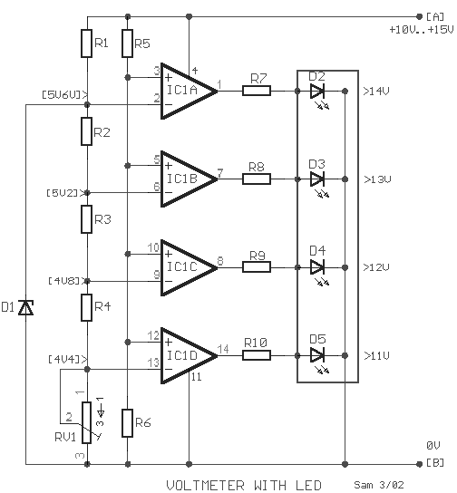
The circuit was developed to create a voltmeter that will be used to test car batteries while showing an indication using LEDs.

  • Voltmeter – a device or an instrument used for measuring the electrical potential difference between two points of either alternating current or direct current electric circuit.
  • LM324 – has internal frequency compensated for unity gain, large DC voltage gain, wide bandwidth, wide power supply range, very low supply current drain, low input biasing current, low input offset voltage, large output voltage swing and differential input voltage range equal to the power supply voltage.
The voltage of a car battery can be measured with the use of a voltmeter as well as the charge left. A typical car battery voltage delivers around 12.6 V under no load condition and will require charging if the voltage reading is at 11.6 V. The measurement of voltage is best recommended during a high current like running the car head lights into high beam. In case the battery rapidly drops its voltage significantly under load, it would require a replacement.

This circuit will function as a comparator and will measure the car battery voltage with an interval or step of 1 V. The voltmeter will be connected across the battery terminals then starting the car. The voltage of the battery should not be measured below 10 V or else it will be considered as low in charge or low in water, since the water level of the battery should be about ¼ of an inch above the plates.

Car Battery Voltmeter with LED Indicator Schematic


Car Battery Voltmeter with LED Indicator

By applying the voltage of the battery in the inverting inputs of the amplifiers, the indicated voltage on the voltmeter is compared with the reference voltages that are produced by the Zener diode D1. The Zener diode is a special kind of diode that permits the flow of current in just one or forward direction as a normal diode, but will also allow in the reverse direction if the voltage is above or larger than a certain value of the breakdown voltage. The measured value is just enough to provide good thermic stability.

The presence of 10K trimmer RV1 is to adjust the degree of voltage that is required or desired while the visual indication will originate from the four LEDs.

R1=1K2
R2-3-4=680R
R5=15K

R6=10K
R7-8-9-10=1K
D1=5V6 /0.5W Zener

D2-3-4-5=LED
IC1=LM324
RV1=10K trimmer

The main use of the car battery voltmeter is to monitor the life and performance of batteries. It can be mounted on the dashboard that shows the battery condition to easily monitor the electrical system voltage while driving. The measurement is done by switching off the engine as well all lights and accessories and switching on the key without starting the engine. The battery is full charge if the voltmeter reads 12 V or more while a voltmeter reading of much less than 12 V signifies the battery is either discharged or failing.
Read More..

Thursday, December 5, 2013

Stereo Balance Indicator

Stereo Balance Indicator
Mechanical deficiencies that affect the reproduction of sound in a stereo amplifier is probably what you are thinking, armpit all the problems have been overcome. And actually bigger role than we know. True, the effect is so small that only a few of us who record it, or divert it to other things.

Most of such shortcomings can be traced back toto the stereo volume control ,maybe two in the no -stepresistance . As a result, the volume difference arises between the two channels and can usually be in balance again by the regulator balance. If you intend to define these differences precisely, stereo balance these indicators can fulfill your purpose.
stereo balance indicator circuit
Stereo Balance Indicator circuit

Quite simply, this circuit by connecting the output terminal and the right channel loudspeaker left channel of the amplifier and feed the same signal, should sinusoid (or cues mono) to the second input channel amplifier. If then the signals at both terminals tarafnya exact same loudspeakers, meters (zero in the middle) in the indicator of this balance will not deviate. However, if the signal level in the left channel is higher than the right channel meter will deviate to the left (or right if the opposite occurs). In this regulatory balance can be set up to read something about zero feet again, then the effect of volume control tracking error can be eliminated.

Trimpot P1 on balance the indicator should be set for full scale meter deflection, when only one channel worked.
Read More..

Monday, December 2, 2013

Pressed Button Sound Indicator

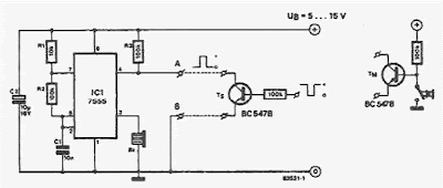
sing this electronic scheme can be made an electronic circuit that allows a sound indication for a button.The circuit is based on a 7555 integrated timer (CMOS version of the well-known ment 555) is connected as a multivibrator astabil .His output is a rectangular pulse with a frequency of 700 Hz, which is used to control a small buzzer.


Pressed Button Sound Indicator Schematic 


Pressed button sound indicator circuit 
 
The circuit will oscillate be prevented if pin 4 of integrated circuit is connected to 0 V.
 
Read More..