Showing posts with label battery. Show all posts

Friday, October 24, 2014

Low Cost Universal Battery Charger Schematic

Low cost solution for charging of both NiCd and NiMh batteries
Here is the circuit diagram of a low cost universal charger for NiCD - NiMH batteries. This circuit is Ideal for car use. It has ability to transform a mains adapter in to a charger . This one can be used to charge cellular phone, toys, portables, video batteries, MP3 players, ... and has selectable charge current. An LED is located in circuit to indicate charging. Can be built on a general purpose PCB or a veroboard. I hope you really like it.
Picture of the circuit:a_low_cost_universal_charger circuit schematic_for_nicd_nimh_batteries 
 A Low Cost Universal Charger Circuit Schematic
Circuit diagram:
a_low_cost_universal_charger_circuit_diagram_for_nicd nimh batteries
A Low Cost Universal Charger Circuit Diagram
Parts:
R1 = 120R-0...5W
R2 = See Diagram
C1 = 220uF-35V
D1 = 1N4007
D2 = 3mm. LED
Q1 = BD135
J1 = DC Input Socket
Specs:
  • Ideal for in car use.
  • LED charge indication.
  • Selectable charge current.
  • Charges Ni Cd or NiMH batteries.
  • Transforms a mains adapter into a charger.
  • Charge cellular phone, toys, portables, video batteries …
Features:
  • LED function indication.
  • Power supply polarity protected.
  • Supply current: same as charge current.
  • Supply voltage: from 6.5VDC to 21VDC (depending on used battery)
  • Charge current (±20%): 50mA, 100mA, 200mA, 300mA, 400mA. (selectable)
Determining the supply voltage:
This table indicates the minimum and maximum voltages to supply the charger. See supply voltage selection chart below.
Example:
To charge a 6V battery a minimum supply voltage of 12V is needed, the maximum voltage is then 15V.
Voltage selection:

supply_voltages_selection_chart_for_ ow cost universal_battery Charger
Voltage Selection Chart For Low Cost Universal Battery Charger

Determining the charge current:
Before building the circuit, you must determinate how much current will be used to charge the battery or battery pack. It is advisable to charge the battery with a current that is 10 times smaller then the battery capacity, and to charge it for about 15 hours. If you double the charge current , then you can charge the battery in half the time. Charge current selection chart is located in diagram.

Example:
A battery pack of 6V / 1000mAh can be charged with 100mA during 15 hours. If you want to charge faster, then a charge current of 200mA can be used for about 7 hours.
Caution:
The higher charge current, the more critical the charge time must be checked. When faster charging is used, it is advisable to discharge the battery completely before charging. Using a charge current of 1/10 of the capacity will expand the lifetime of the battery. The charge time can easily be doubled without damaging the battery.
Note:
  • Mount the transistor together with the heatsink on the PCB, bend the leads as necessary. Take care that the metal back of the transistor touches the heatsink. Check that the leads of the transistor do not touch the heatsink.
Source : http://www.ecircuitslab.com
Read More..

Solar Powered SLA Battery Maintenance

This circuit was designed to ‘baby-sit’ SLA (sealed lead-acid or ‘gel’) batteries using freely available solar power. SLA batteries suffer from relatively high internal energy loss which is not normally a problem until you go on holidays and disconnect them from their trickle current charger. In some cases, the absence of trickle charging current may cause SLA batteries to go completely flat within a few weeks. The circuit shown here is intended to prevent this from happening. Two 3-volt solar panels, each shunted by a diode to bypass them when no electricity is generated, power a MAX762 step-up voltage converter IC. 

Circuit diagram:
Solar Powered SLA Battery-Maintenance-Circuit-Diagram
Solar Powered SLA Battery Maintenance Circuit Diagram

The ‘762 is the 15-volt-out version of the perhaps more familiar MAX761 (12 V out) and is used here to boost 6 V to 15 V.C1 and C2 are decoupling capacitors that suppress high and low frequency spurious components produced by the switch-mode regulator IC. Using Schottky diode D3, energy is stored in inductor L1 in the form of a magnetic field. When pin 7 of IC1 is open-circuited by the internal switching signal, the stored energy is diverted to the 15-volt output of the circuit. The V+ (sense) input of the MAX762, pin 8, is used to maintain the output voltage at 15 V. C4 and C5 serve to keep the ripple on the output voltage as small as possible. R1, LED D4 and pushbutton S1 allow you to check the presence of the 15-V output voltage.

D5 and D6 reduce the 15-volts to about 13.6 V which is a frequently quoted nominal standby trickle charging voltage for SLA batteries. This corresponds well with the IC’s maximum, internally limited, output current of about 120 mA. The value of inductor L1 is not critical — 22 µH or 47 µH will also work fine. The coil has to be rated at 1 A though in view of the peak current through it. The switching frequency is about 300 kHz. A suggestion for a practical coil is type M from the WEPD series supplied by Würth (www.we-online.com). Remarkably, Würth supply one-off inductors to individual customers. 


Author : Myo Min
Read More..

Flat Battery Indicator

This small circuit was developed to monitor the battery in a model hovercraft. The lift in the model is produced by an electric motor driving a fan. To avoid the possibility of discharging the rechargeable battery pack too deeply, the design lights a conspicuous LED mounted on the model when a preset threshold voltage is reached. The circuit only uses a few components, which helps keep the total weight of the model down. The circuit connects to the model only across the two points where the voltage to be monitored can be measured. These also supply power to the circuit.

The best place to connect the circuit is not at the battery terminals, but rather at the motor connections. The circuit is suitable for use with nominal battery voltages of 4.8 V to 9.6 V (four to eight 1.2 V cells). For example, if there are six cells in the battery, its nominal terminal voltage will be 7.2 V. A discharge threshold voltage of around 1 V per cell is appropriate, which means that for six cells the threshold is 6 V. We now need to set the voltage UZ across the adjustable Zener diode D1 (an LM431) to about 0.5 V less than the threshold voltage at which we want LED D2 to light.
This voltage is controlled by the choice of the value of resistor R1. As indicated in the circuit diagram, this is done with the help of a trimmer potentiometer (R1.A) with a fixed resistor (R1.B) in series. Using the suggested values (10 kΩ for both the potentiometer and the fixed resistor) allows the discharge threshold voltage to be set between about 5.5 V and 8 V. For lower or higher voltages R1.B should be made correspondingly smaller or larger. Once the desired value of UZ has been set the total resistance (R1.A plus R1.B) can be measured and a single fixed-value resistor of this value substituted at R1.

In the example mentioned of a six-cell battery, a voltage of 7.2 V will appear at the emitter of T1 when the battery is charged. At its base is UZ, which should be 5.5 V (6 V – 0.5 V) in the case of a discharge threshold voltage of 6 V. As long as the battery voltage remains at least 0.5 V higher than UZ, T1 will conduct and T2 will block, with the result that LED D2 will not light. If the battery voltage should fall below about 6 V (UZ + 0.5 V), T1 will block, T2 will conduct and LED D2 will light. To ensure stable operation of the circuit R6 provides a small amount of switching hysteresis. By adjusting the resistor value between 100 kΩ and 220 kΩ the amount of hysteresis can be varied.

The current drawn by the circuit itself is less than 5 mA (as measured with a battery voltage of 7.2 V). When the LED lights an additional 10 mA (the LED current) is drawn, for a total of around 15 mA. The adjustable Zener diode can be replaced by a fixed Zener with a voltage 0.5 V less than the desired threshold. Resistors R1 and R2 can then be dispensed with. A flashing LED can be used for D2 (without series resistor R7). An acoustic alarm can be provided by replacing D2 and R7 by a DC buzzer with a suitable operating voltage.
Read More..

Battery Discharger Using Discrete Components

The battery discharger published in this website may be improved by adding a Schottky diode (D3). This ensures that a NiCd cell is discharged not to 0.6–0.7 V, but to just under 1 V as recommended by the manufacturers. An additional effect is then that light-emitting diode D2 flashes when the battery connected to the terminals is flat. The circuit in the diagram is based on an astable multivibrator operating at a frequency of about 25 kHz. When transistor T2 conducts, a current flows through inductor L1, whereupon energy is stored in the resulting electromagnetic field. When T2 is cut off, the field collapses, whereupon a counter-emf is produced at a level that exceeds the forward voltage (about 1.6 V) of D2.

Battery Discharger Circuit Diagram0

A current then flows through the diode so that this lights. Diode D1 prevents the current flowing through R4 and C2. This process is halted only when the battery voltage no longer provides a sufficient base potential for the transistors. In the original circuit, this happened at about 0.65 V. The addition of the forward bias of D3 (about 0.3 V), the final discharge voltage of the battery is raised to 0.9–1.0 V. Additional resistors R5 and R6 ensure that sufficient current flows through D3. When the battery is discharged to the recommended level, it must be removed from the discharger since, in contrast to the original circuit, a small current continues to flow through D3, R2-R3, and R5-R6 until the battery is totally discharged.

The flashing of D2 when the battery is nearing recommended discharge is caused by the increasing internal resistance of the battery lowering the terminal voltage to below the threshold level. If no current flows, the internal resistance is of no consequence since the terminal voltage rises to the threshold voltage by taking some energy from the battery. When the discharge is complete to the recommended level, the LED goes out. It should therefore be noted that the battery is discharged sufficiently when the LED begins to flash.


http://www.ecircuitslab.com/
Read More..

Thursday, September 18, 2014

Battery Juicer

More and more electronic devices are portable and run off batteries. It is no surprise, then, that so many flat batteries find their way into the bin and often far too early. When a set of batteries can no longer run some device for example, a flashgun the cells are not necessarily completely discharged. If you put an apparently unserviceable AA-size cell into a radio-controlled clock with an LCD display it will run for months if not years.

 Of course not every partially discharged cell can be put in a clock. The circuit presented here lets you squeeze the last Watt-second out of your batteries, providing a bright ‘night light’ - for free! The circuit features a TBA820M, a cheap audio power amplifier capable of operating from a very low supply voltage. Here it is connected as an astable multivibrator running at a frequency of around 13 kHz. Together with the two diodes and electrolytic capacitor this forms a DC-DC converter which can almost double the voltage from between four and eight series-connected AA-, C- or D-size cells, or from a PP3-style battery.

Circuit diagram:
Battery-Juicer Circuit-Diagram
Battery Juicer Circuit Diagram

The DC-DC converter is followed by a constant current source which drives the LED. This protects the expensive white LED: the voltages obtained from old batteries can vary considerably. With the use of the DC-DC converter and 20 mA constant current source a much greater range of usable input voltages is achieved, particularly helpful at the lower end of the range when old batteries are used. With the constant current source on its own the white LED would not be adequately bright when run from low voltages.

An additional feature is the ‘automatic eye’. The LDR detects when the normal room lighting is switched on or when the room is lit by sunlight: its resistance decreases. This reduces the UBE of the transistor below 0.7 V, the BC337 turns off and deactivates the LED. This prolongs further the life of the old batteries. A further LDR across capacitor C reduces the quiescent current of the circuit to just 4mA (at 4V). Light from the white LED must of course not fall on the LDR, or the current saving function will not work.


Author : W. Zeiller
Read More..

Lead Acid Battery Protector

The circuit described here can be used to  ensure  that  a  12 V  sealed  lead  acid  (SLA)  gel battery isn’t discharged too deeply. The  principal part of the circuit is a bistable relay,  which is driven by the output of an op amp. 

Circuit diagram :
Lead Acid Battery Protector dd
Lead Acid Battery Protector Circuit Diagram
The battery voltage is first reduced via D1, R1,  P1 and R2, and then continuously compared  with a reference voltage set up by diode D2.  When the battery discharges too much and  its terminal voltage drops below the level  set by P1, the output of the opamp becomes  High, which causes the relay to toggle. This  in turn isolates the load from the battery. The  battery can be reconnected via S1 once the  battery has been replaced or recharged. 

The relay used in the prototype is a 5 V bistable type made by Omron (G6AK-234P-ST-US  5 VDC). The two windings of the relay each  have a resistance of 139 Ω (for the RAL-D 5  W-K made by Fujitsu this is 167 Ω). When the  battery voltage starts to become too low and  the relay is being reset the current consumption of the circuit is about 45 mA. Shortly  after the load has been disconnected, when the battery voltage rises above the reference  voltage again, the reset coil will no longer be  powered and the current consumption drops  back to about 2.5 mA. 

The range of P1 has intentionally been kept  small. With a reference voltage of 5.6 V (D2)  and a voltage drop of 0.64 V across D1, the circuit reacts within a voltage span of 11.5 V and  11.8 V. This range is obviously dependent on the zener diode used and the tolerance. 

For a greater span you can use a larger value  for P1 without any problems. With the potentiometer at its mid setting the circuit switches  at about 11.6 V.
 
 
Author : Jürgen Stannieder
Read More..

Battery powered Headphone Amplifier

Low distortion Class-B circuitry 6V Battery Supply
Some lovers of High Fidelity headphone listening prefer the use of battery powered headphone amplifiers, not only for portable units but also for home "table" applications. This design is intended to fulfil their needs and its topology is derived from the Portable Headphone Amplifier featuring an NPN/PNP compound pair emitter follower output stage. An improved output driving capability is gained by making this a push-pull Class-B arrangement. Output power can reach 100mW RMS into a 16 Ohm load at 6V supply with low standing and mean current consumption, allowing long battery duration. The single voltage gain stage allows the easy implementation of a shunt-feedback circuitry giving excellent frequency stability.
Circuit diagram :
Battery-powered Headphone Amplifier Circuit diagram

Notes:
  • For a Stereo version of this circuit, all parts must be doubled except P1, SW1, J2 and B1.
  • Before setting quiescent current rotate the volume control P1 to the minimum, Trimmer R6 to maximum resistance and Trimmer R3 to about the middle of its travel.
  • Connect a suitable headphone set or, better, a 33 Ohm 1/2W resistor to the amplifier output.
  • Switch on the supply and measure the battery voltage with a Multimeter set to about 10Vdc fsd.
  • Connect the Multimeter across the positive end of C4 and the negative ground.
  • Rotate R3 in order to read on the Multimeter display exactly half of the battery voltage previously measured.
  • Switch off the supply, disconnect the Multimeter and reconnect it, set to measure about 10mA fsd, in series to the positive supply of the amplifier.
  • Switch on the supply and rotate R6 slowly until a reading of about 3mA is displayed.
  • Check again the voltage at the positive end of C4 and readjust R3 if necessary.
  • Wait about 15 minutes, watch if the current is varying and readjust if necessary.
  • Those lucky enough to reach an oscilloscope and a 1KHz sine wave generator, can drive the amplifier to the maximum output power and adjust R3 in order to obtain a symmetrical clipping of the sine wave displayed.
Technical data:
Output power (1KHz sinewave):
    16 Ohm: 100mW RMS
    32 Ohm: 60mW RMS
    64 Ohm: 35mW RMS
    100 Ohm: 22.5mW RMS
    300 Ohm: 8.5mW RMS
Sensitivity:
    160mV input for 1V RMS output into 32 Ohm load (31mW)
    200mV input for 1.27V RMS output into 32 Ohm load (50mW)
Frequency response @ 1V RMS:
    flat from 45Hz to 20KHz, -1dB @ 35Hz, -2dB @ 24Hz
Total harmonic distortion into 16 Ohm load @ 1KHz:
    1V RMS (62mW) 0.015% 1.27V RMS (onset of clipping, 100mW) 0.04%
Total harmonic distortion into 16 Ohm load @ 10KHz:
    1V RMS (62mW) 0.05% 1.27V RMS (onset of clipping, 100mW) 0.1%
Unconditionally stable on capacitive loads


Source : red circuits
Read More..

Thursday, February 27, 2014

Flashing LED Battery status Indicator

Signals when an on-circuit battery is exhausted 5V to 12V operating voltage
A Battery-status Indicator circuit can be useful, mainly to monitor portable Test-gear instruments and similar devices. LED D1 flashes to attire the users attention, signaling that the circuit is running, so it will not be left on by mistake. The circuit generates about two LED flashes per second, but the mean current drawing will be about 200µA. Transistors Q1 and Q2 are wired as an uncommon complementary astable multivibrator: both are off 99% of the time, saturating only when the LED illuminates, thus contributing to keep very low current consumption. 

Circuit diagram :
Flashing-LED Battery
Flashing-LED Battery-status Indicator Circuit Diagram

The circuit will work with battery supply voltages in the 5 - 12V range and the LED flashing can be stopped at the desired battery voltage (comprised in the 4.8 - 9V value) by adjusting Trimmer R4. This range can be modified by changing R3 and/or R4 value slightly.

When the battery voltage approaches the exhausting value, the LED flashing frequency will fall suddenly to alert the user. Obviously, when the battery voltage has fallen below this value, the LED will remain permanently off. To keep stable the exhausting voltage value, diode D1 was added to compensate Q1 Base-Emitter junction changes in temperature. The use of a Schottky-barrier device (e.g. BAT46, 1N5819 and the like) for D1 is mandatory: the circuit will not work if a common silicon diode like the 1N4148 is used in its place.

Parts :
R1,R7__________220R  1/4W Resistors
R2_____________120K  1/4W Resistor
R3_______________5K6 1/4W Resistor
R4_______________5K  1/2W Trimmer Cermet or Carbon
R5______________33K  1/4W Resistor
R6_____________680K  1/4W Resistor
R8_____________100K  1/4W Resistor
R9_____________180R  1/4W Resistor
C1,C2____________4µ7  25V Electrolytic Capacitors
D1____________BAT46  100V 150mA Schottky-barrier Diode
D2______________LED  Red 5mm.
Q1____________BC547   45V 100mA NPN Transistor
Q2____________BC557   45V 100mA PNP Transistor
B1_______________5V to 12V Battery supply
Notes :
  • Mean current drawing of the circuit can be reduced further on by raising R1, R7 and R9 values.
Source : Red Circuits
Read More..

Tuesday, February 4, 2014

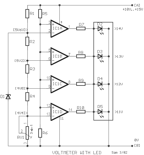
Car Battery Voltmeter with LED Indicator

The circuit was developed to create a voltmeter that will be used to test car batteries while showing an indication using LEDs.

  • Voltmeter – a device or an instrument used for measuring the electrical potential difference between two points of either alternating current or direct current electric circuit.
  • LM324 – has internal frequency compensated for unity gain, large DC voltage gain, wide bandwidth, wide power supply range, very low supply current drain, low input biasing current, low input offset voltage, large output voltage swing and differential input voltage range equal to the power supply voltage.
The voltage of a car battery can be measured with the use of a voltmeter as well as the charge left. A typical car battery voltage delivers around 12.6 V under no load condition and will require charging if the voltage reading is at 11.6 V. The measurement of voltage is best recommended during a high current like running the car head lights into high beam. In case the battery rapidly drops its voltage significantly under load, it would require a replacement.

This circuit will function as a comparator and will measure the car battery voltage with an interval or step of 1 V. The voltmeter will be connected across the battery terminals then starting the car. The voltage of the battery should not be measured below 10 V or else it will be considered as low in charge or low in water, since the water level of the battery should be about ¼ of an inch above the plates.

Car Battery Voltmeter with LED Indicator Schematic


Car Battery Voltmeter with LED Indicator

By applying the voltage of the battery in the inverting inputs of the amplifiers, the indicated voltage on the voltmeter is compared with the reference voltages that are produced by the Zener diode D1. The Zener diode is a special kind of diode that permits the flow of current in just one or forward direction as a normal diode, but will also allow in the reverse direction if the voltage is above or larger than a certain value of the breakdown voltage. The measured value is just enough to provide good thermic stability.

The presence of 10K trimmer RV1 is to adjust the degree of voltage that is required or desired while the visual indication will originate from the four LEDs.

R1=1K2
R2-3-4=680R
R5=15K

R6=10K
R7-8-9-10=1K
D1=5V6 /0.5W Zener

D2-3-4-5=LED
IC1=LM324
RV1=10K trimmer

The main use of the car battery voltmeter is to monitor the life and performance of batteries. It can be mounted on the dashboard that shows the battery condition to easily monitor the electrical system voltage while driving. The measurement is done by switching off the engine as well all lights and accessories and switching on the key without starting the engine. The battery is full charge if the voltmeter reads 12 V or more while a voltmeter reading of much less than 12 V signifies the battery is either discharged or failing.
Read More..

Saturday, January 25, 2014

Nicad Battery charger include voltage limiting

In this my circuit , which is one of a series of simple battery charger , but this circuit to charger the Nicad battery . This circuit included with current and voltage limting . Why use it ?? because with current voltage you can choose voltage to charge a battery , and the limiting voltage use limit voltage if the battery is fully, because if battery fully that damaged quickly.

See this schematic below :


Click to view Enlarge


Lamp 1 will glow brightly and the LED will be out when the battery is low or run out and the circuit is processing being to charged , but the LED will bright and the light dim when the battery is almost ready. Output voltage between 12 to 14 volt with current 100 mA.
Read More..

Thursday, January 9, 2014

Simple 6V charger battery circuit

This is very simple charger 9V - 30V battery charger with main operation by IC LM317L and 2N222 transistor. Direct input DC voltage , the recomended capacitor is 1000uf. It can be filtering Output voltage and make long-lasting battery. And easy to make this circuit , without using the PCB would be able to.
See the Charger Schematic and troubleshooting below :
If it cant working , then the mistakes and keeping the following :
  • Check input voltage, whether working or not.
  • Check the installation of the pins of components.
  • Chek transistor , at input voltage , base , and output voltage.
  • Check IC input voltage and output voltage , there or not.

Thank  you 4 visiting my blog.
Read More..

Thursday, December 5, 2013

Mosfet Battery Charger

Battery Charger series with the MOSFETs are designed to charge batteries from an AC current source charging current with a maximum capacity of 1A, and can be modified in order to provide a higher flow by replacing the value of Q1, R1, D1-D5, and T1 with a greater ability high on "battery charger circuit with mosfet" this. The series charger is working at the point of maximum load line of the ability of Q1, so that Q1 needs to get serious attention to cool it and make re-assembly croscek this battery charger before use.
Mosfet Battery Charger
NiCad batteries have the capacity specifications in units of mAh (Mili Ampere Hour), which is defined as "C". The value of this interpretation of capacity C that can be saved by tesebut NiCad battery. To charge the NiCad battery in a normal (not Fast Charge) used in the formulation of charging current 0.1 C NiCad batteries are in charge for 12 hours. Suppose the battery capacity is 4000mAH then filling current 400mA for 12 hours. The advantage of charging the battery by 0.1 C this formula is to create long-lasting battery is not easily damaged or otherwise not charge the battery too quickly run out.

Output current from the battery charger circuit with mosfet is controlled by the sum of the zener reference diode and the base-emitter connection of PNP transistors. PNP transistor provides negative feedback to the gate MOSFETs. As seen in the scheme. Flow output is determined by the value of R1 is determined by:
R1 = 3.2Volts/Iout
Power dissipation of R1 will be the same:
PR1 = 3.2Volts Iout *
R1 resource capacity and heatsink Q1 adjusted charging current.
Read More..