Showing posts with label charger. Show all posts

Friday, October 24, 2014

Low Cost Universal Battery Charger Schematic

Low cost solution for charging of both NiCd and NiMh batteries
Here is the circuit diagram of a low cost universal charger for NiCD - NiMH batteries. This circuit is Ideal for car use. It has ability to transform a mains adapter in to a charger . This one can be used to charge cellular phone, toys, portables, video batteries, MP3 players, ... and has selectable charge current. An LED is located in circuit to indicate charging. Can be built on a general purpose PCB or a veroboard. I hope you really like it.
Picture of the circuit:a_low_cost_universal_charger circuit schematic_for_nicd_nimh_batteries 
 A Low Cost Universal Charger Circuit Schematic
Circuit diagram:
a_low_cost_universal_charger_circuit_diagram_for_nicd nimh batteries
A Low Cost Universal Charger Circuit Diagram
Parts:
R1 = 120R-0...5W
R2 = See Diagram
C1 = 220uF-35V
D1 = 1N4007
D2 = 3mm. LED
Q1 = BD135
J1 = DC Input Socket
Specs:
  • Ideal for in car use.
  • LED charge indication.
  • Selectable charge current.
  • Charges Ni Cd or NiMH batteries.
  • Transforms a mains adapter into a charger.
  • Charge cellular phone, toys, portables, video batteries …
Features:
  • LED function indication.
  • Power supply polarity protected.
  • Supply current: same as charge current.
  • Supply voltage: from 6.5VDC to 21VDC (depending on used battery)
  • Charge current (±20%): 50mA, 100mA, 200mA, 300mA, 400mA. (selectable)
Determining the supply voltage:
This table indicates the minimum and maximum voltages to supply the charger. See supply voltage selection chart below.
Example:
To charge a 6V battery a minimum supply voltage of 12V is needed, the maximum voltage is then 15V.
Voltage selection:

supply_voltages_selection_chart_for_ ow cost universal_battery Charger
Voltage Selection Chart For Low Cost Universal Battery Charger

Determining the charge current:
Before building the circuit, you must determinate how much current will be used to charge the battery or battery pack. It is advisable to charge the battery with a current that is 10 times smaller then the battery capacity, and to charge it for about 15 hours. If you double the charge current , then you can charge the battery in half the time. Charge current selection chart is located in diagram.

Example:
A battery pack of 6V / 1000mAh can be charged with 100mA during 15 hours. If you want to charge faster, then a charge current of 200mA can be used for about 7 hours.
Caution:
The higher charge current, the more critical the charge time must be checked. When faster charging is used, it is advisable to discharge the battery completely before charging. Using a charge current of 1/10 of the capacity will expand the lifetime of the battery. The charge time can easily be doubled without damaging the battery.
Note:
  • Mount the transistor together with the heatsink on the PCB, bend the leads as necessary. Take care that the metal back of the transistor touches the heatsink. Check that the leads of the transistor do not touch the heatsink.
Source : http://www.ecircuitslab.com
Read More..

Saturday, January 25, 2014

Nicad Battery charger include voltage limiting

In this my circuit , which is one of a series of simple battery charger , but this circuit to charger the Nicad battery . This circuit included with current and voltage limting . Why use it ?? because with current voltage you can choose voltage to charge a battery , and the limiting voltage use limit voltage if the battery is fully, because if battery fully that damaged quickly.

See this schematic below :


Click to view Enlarge


Lamp 1 will glow brightly and the LED will be out when the battery is low or run out and the circuit is processing being to charged , but the LED will bright and the light dim when the battery is almost ready. Output voltage between 12 to 14 volt with current 100 mA.
Read More..

Thursday, January 9, 2014

Simple 6V charger battery circuit

This is very simple charger 9V - 30V battery charger with main operation by IC LM317L and 2N222 transistor. Direct input DC voltage , the recomended capacitor is 1000uf. It can be filtering Output voltage and make long-lasting battery. And easy to make this circuit , without using the PCB would be able to.
See the Charger Schematic and troubleshooting below :
If it cant working , then the mistakes and keeping the following :
  • Check input voltage, whether working or not.
  • Check the installation of the pins of components.
  • Chek transistor , at input voltage , base , and output voltage.
  • Check IC input voltage and output voltage , there or not.

Thank  you 4 visiting my blog.
Read More..

Thursday, December 12, 2013

USB Charger Using IC MAX1555

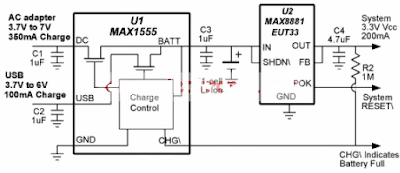
This USB charger circuit is designed using the MAX1555 IC circuit manufactured by Maxim Semiconductor This MAX1555 USB charger can be used using the USB power or AC power.This MAX1555 charger is charging at 100mA from USB port and the maximum charging current increases to 350mA if the USB the AC adapter is connected . If both power types are connected in the same time the AC adapter is automatically given precedence. 

USB Charger Circuit diagram

MAX1555 USB Charger

This charger can be used for small devices like : PDAs ,Cell Phones , Digital Cameras , MP3 Players and other.The charger can be used for Li-Ion or Li-Polymer batteries . The electronic project charger circuit require a input voltage between 3V and 7 V and deliver an 3.3 V output voltage.As you can see in the circuit diagram , before the IC is connected the MAX8881 linear regulator IC which is capable to deliver up to 200mA.The MAX1881 is specially designed for battery-powered applications where reverse battery protection and long battery life are critical.
Read More..

Thursday, December 5, 2013

Mosfet Battery Charger

Battery Charger series with the MOSFETs are designed to charge batteries from an AC current source charging current with a maximum capacity of 1A, and can be modified in order to provide a higher flow by replacing the value of Q1, R1, D1-D5, and T1 with a greater ability high on "battery charger circuit with mosfet" this. The series charger is working at the point of maximum load line of the ability of Q1, so that Q1 needs to get serious attention to cool it and make re-assembly croscek this battery charger before use.
Mosfet Battery Charger
NiCad batteries have the capacity specifications in units of mAh (Mili Ampere Hour), which is defined as "C". The value of this interpretation of capacity C that can be saved by tesebut NiCad battery. To charge the NiCad battery in a normal (not Fast Charge) used in the formulation of charging current 0.1 C NiCad batteries are in charge for 12 hours. Suppose the battery capacity is 4000mAH then filling current 400mA for 12 hours. The advantage of charging the battery by 0.1 C this formula is to create long-lasting battery is not easily damaged or otherwise not charge the battery too quickly run out.

Output current from the battery charger circuit with mosfet is controlled by the sum of the zener reference diode and the base-emitter connection of PNP transistors. PNP transistor provides negative feedback to the gate MOSFETs. As seen in the scheme. Flow output is determined by the value of R1 is determined by:
R1 = 3.2Volts/Iout
Power dissipation of R1 will be the same:
PR1 = 3.2Volts Iout *
R1 resource capacity and heatsink Q1 adjusted charging current.
Read More..

Wednesday, December 4, 2013

Variable charger circuit

Indeed the accu charger circuit , the voltage required must be in accordance with voltage batteries , such accu 12 volts the the output voltage should not be above 12 volts and 12 volts should not be too down. If it does not comply with the required voltage , it will make the batteries or accu quickly broken. But not to worry to find the right voltage to charge to accu, the voltage control circuit is equipped to facilitate in determining the voltage.
Transformer
Primary : 33 turns #22
Secondary : 45 turns #22
Core : Ferroxcube 203 F 181.3C3
Read More..

Friday, November 29, 2013

Simple accu charger circuit

charger schematics
Accu charger circuit is very simple and easy to make, because it only requires a few components are also not more than 10 components. Besides easy charger circuit is also very cheap and very efficient. 


This circuit requires power supply from a transformer that comes from an AC voltage 220 ​​and diuturunkan be 12-13 volts and then enter to-circuit and 12 Volt DC output allows for charging 12V ​​battery

charger schematics circuit
Simple charger schematics
Read More..