Showing posts with label car. Show all posts
Showing posts with label car. Show all posts
Tuesday, February 4, 2014
Car Battery Voltmeter with LED Indicator
The circuit was developed to create a voltmeter that will be used to test car batteries while showing an indication using LEDs.
This circuit will function as a comparator and will measure the car battery voltage with an interval or step of 1 V. The voltmeter will be connected across the battery terminals then starting the car. The voltage of the battery should not be measured below 10 V or else it will be considered as low in charge or low in water, since the water level of the battery should be about ¼ of an inch above the plates.
Car Battery Voltmeter with LED Indicator Schematic
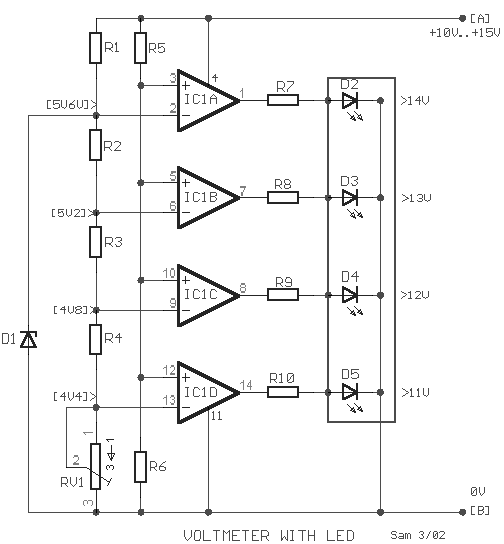
By applying the voltage of the battery in the inverting inputs of the amplifiers, the indicated voltage on the voltmeter is compared with the reference voltages that are produced by the Zener diode D1. The Zener diode is a special kind of diode that permits the flow of current in just one or forward direction as a normal diode, but will also allow in the reverse direction if the voltage is above or larger than a certain value of the breakdown voltage. The measured value is just enough to provide good thermic stability.
The presence of 10K trimmer RV1 is to adjust the degree of voltage that is required or desired while the visual indication will originate from the four LEDs.
R1=1K2
R2-3-4=680R
R5=15K
R6=10K
R7-8-9-10=1K
D1=5V6 /0.5W Zener
D2-3-4-5=LED
IC1=LM324
RV1=10K trimmer
The main use of the car battery voltmeter is to monitor the life and performance of batteries. It can be mounted on the dashboard that shows the battery condition to easily monitor the electrical system voltage while driving. The measurement is done by switching off the engine as well all lights and accessories and switching on the key without starting the engine. The battery is full charge if the voltmeter reads 12 V or more while a voltmeter reading of much less than 12 V signifies the battery is either discharged or failing.
- Voltmeter – a device or an instrument used for measuring the electrical potential difference between two points of either alternating current or direct current electric circuit.
- LM324 – has internal frequency compensated for unity gain, large DC voltage gain, wide bandwidth, wide power supply range, very low supply current drain, low input biasing current, low input offset voltage, large output voltage swing and differential input voltage range equal to the power supply voltage.
This circuit will function as a comparator and will measure the car battery voltage with an interval or step of 1 V. The voltmeter will be connected across the battery terminals then starting the car. The voltage of the battery should not be measured below 10 V or else it will be considered as low in charge or low in water, since the water level of the battery should be about ¼ of an inch above the plates.
Car Battery Voltmeter with LED Indicator Schematic
By applying the voltage of the battery in the inverting inputs of the amplifiers, the indicated voltage on the voltmeter is compared with the reference voltages that are produced by the Zener diode D1. The Zener diode is a special kind of diode that permits the flow of current in just one or forward direction as a normal diode, but will also allow in the reverse direction if the voltage is above or larger than a certain value of the breakdown voltage. The measured value is just enough to provide good thermic stability.
The presence of 10K trimmer RV1 is to adjust the degree of voltage that is required or desired while the visual indication will originate from the four LEDs.
R1=1K2
R2-3-4=680R
R5=15K
R6=10K
R7-8-9-10=1K
D1=5V6 /0.5W Zener
D2-3-4-5=LED
IC1=LM324
RV1=10K trimmer
The main use of the car battery voltmeter is to monitor the life and performance of batteries. It can be mounted on the dashboard that shows the battery condition to easily monitor the electrical system voltage while driving. The measurement is done by switching off the engine as well all lights and accessories and switching on the key without starting the engine. The battery is full charge if the voltmeter reads 12 V or more while a voltmeter reading of much less than 12 V signifies the battery is either discharged or failing.

Tuesday, November 26, 2013
50W car audio amplifier schematic circuits
 Car power amplifier uses SI1050GL IC as the main amplifier. The output power 50 Watt 8 ohm mono impedance. Up to 25 Volt DC voltage. with source voltage of this amplifier car battery has to work.
Minimum of 12 Volt battery voltage, less than a sound or audio is issued less than the maximum and less good. You can assemble this circuit amplifier with a schema like this.

Part List
R1 = 100K
R2 = 1R
C1 = 2.2uF
C2 = 22uFC3 = 100uF
C4 = 0.1uF
C5 = 100uFU1 = SI1050GL
If you want to make stereo amplifier , you must required multiply the two of components.
Friday, November 22, 2013
Car power amplifier with TA82010AH
IC TA8210AH is ic often used in amplifiers used in the room, It is suitable for power amplifiers car speakers taht fit and wear ell, surely this amplifier circuit works with a maximum also high quality. Supply voltage is not too high , only 12 VDC and is also good at high current. For high current amplifier power of the stronger . You can use the batteries that have current 10 A or higher . Power output up to 200W stereo with 8 Ohm impedance.
Part List :
R1 =1K
R2 =50K trim
R3 =1K
R4 =50K trim
R5 =680R
R6 =680R
R7 =150K
R8 =2R2
R9 =2R2
R10=2R2
R11=2R2
C1 =1uF
C2 =1uF
C3 =47uF
C4 =47uF
C5 =100n/400V
C6 =220uF
C7 =220uF
C8 =100n/400V
C9 =100n/400V
C10=100n/400V
IC1=TA8210AH
X2-3=in R
X2-2=gnd
X2-1=in L
X1-1,X1-2=Out R
X1-3,X1-4=Out L

Subscribe to:
Posts (Atom)