Showing posts with label amplifier. Show all posts

Friday, October 17, 2014

Build a Simple Audio Amplifier 2800W Circuit Diagram

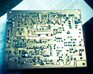
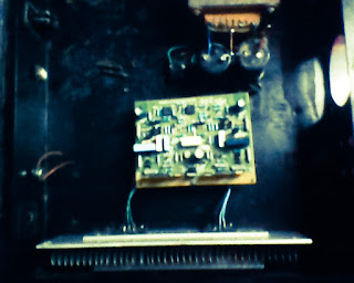
How to Build a Simple Audio Amplifier 2800W Circuit Diagram. This is a Mono high power amplifier is actually a powerful 1400 W, but if this high power amplifier circuit is doubled and you want to create stereo, high power amplifier the necessary components and pcb requires two-fold. So if the stereo high power amplifier 2 X 1400W. Schematic Circuit diagram is still less by looking at the circuit that was so below, the finished circuit has been added with a gains using JRC4558 IC by the two and the picture ic where it can be seen below. 

For circuit buffers, drivers, and booster use multiple transistors and other components (can be seen listed component). And high power amplifier project that is so below is just part of the buffer and driver while the booster has not been made​​. For additional transistors in the booster or high power amplifier end scheme can be found Booster output power amplifier.

 Audio Amplifier 2800W Circuit Diagram


Part List :

Resistor
R1_____560Ω
R2_____100Ω
R3_____2K2Ω
R4_____560Ω
R5_____1Ω
R6_____27KΩ
R7_____10KΩ
R8_____100Ω
R9_____100Ω
R10____100Ω
R11____12KΩ
R12____100Ω
R13____100Ω
R14____100Ω
R15____27KΩ
R16____2K2Ω
R17____560Ω
R18____100Ω
R19____10KΩ
R20____330Ω
R21____47Ω 2W
R22____56Ω
R23____2K2Ω
R24____22Ω
R25____56Ω
R26____180Ω
R27____500-1KΩ Trim
R28____560Ω
R29____56Ω
R30____56Ω
R31____22Ω 1W
R32____5Ω6 2W
R33____10Ω
R34____180Ω
R35____100Ω
R36____22Ω 2W
R37____180Ω
R38____56Ω
R39____47Ω 2W
R40____5Ω6 2W
R41____10Ω
R42____10Ω
R43____10Ω
R45____10Ω
R46____0.22Ω 5W
R47____0.22Ω 5W
R48____0.22Ω 5W
R49____0.22Ω 5W
R50____10Ω 5W

Capacitor
C1_____1цF
C2_____1.5nF
C3_____0.1цF 250-275V
C4_____0.1цF 250-275VC5_____100nF
C6_____100цF 50V
C7_____39pF
C8_____330pF
C9_____330pF
C10____330pF
C11____47nF 250-275V
C12____220nF 250-275V

Transistor
T1_____MJE340
T2_____2N5551 / C2240
T3_____2N5551 / C2240
T4_____2N5551 / C2240
T5_____2N5551 / C2240
T6_____2N5401 / BF423
T7_____2N5401 / BF423
T8_____2N5401 / BF423
T9_____2N5401 / BF423
T10____MJE350
T11____B1186
T12____TIP127
T13____D1763
T14____D1763
T15____B1186
T16____C5198
T17____A1941
T18____2SC2922 / MJ15024G
T19____2SC2922 / MJ15024G
T20____2SA1216 / MJ15025G
T21____2SA1216 / MJ15025G


Sourced by SIGMA-4 Madiun ©
Read More..

Saturday, October 11, 2014

Mini Portable Guitar Amplifier

Can be fitted into a packet of cigarettes, Also suitable as Fuzz-box
This small amplifier was intended to be used in conjunction with an electric guitar to do some low power monitoring, mainly for practice, either via an incorporated small loudspeaker or headphones. The complete circuit, loudspeaker, batteries, input and output jacks can be encased in a small box having the dimensions of a packet of cigarettes, or it could be fitted also into a real packet of cigarettes like some ready-made units available on the market.

This design can be used in three different ways:
  • Loudspeaker amplifier: when powered by a 9V alkaline battery it can deliver about 1.5W peak output power to the incorporated loudspeaker.
  • Headphone amplifier or low power loudspeaker amplifier: when powered by a 3V battery (2x1.5V cells) it can drive any headphone set type at a satisfactory output power level or deliver to the incorporated loudspeaker about 60mW of output power. This configuration is useful for saving battery costs.
  • Fuzz-box: when powered by a 3V battery (2x1.5V cells) and having its output connected to a guitar amplifier input the circuit will behave as a good Fuzz-box, showing an output square wave with marked rounded corners, typical of valve-circuits output when driven into saturation.
Circuit diagram:
Mini Portable Guitar Amplifier
Mini Guitar Amplifier Circuit Diagram
Parts:
R1__________22K 1/4W Resistor
C1__________10µF 25V Electrolytic Capacitor
C2__________100nF 63V Polyester or Ceramic Capacitor
C3__________220µF 25V Electrolytic Capacitor
IC1_________TDA7052 Audio power amplifier IC
J1,J2_______6.3mm Stereo Jack sockets (switched)
SPKR_______8 Ohm Loudspeaker (See Notes)
B1_________9V PP3 Battery or 3V Battery (2 x 1.5V AA, AAA Cells in series etc.)
Clip for PP3 Battery or socket for 2 x 1.5V AA or AAA Cells
Notes:
  • For the sake of simplicity and compactness, this unit employs a dual bridge IC amplifier and a few other parts. For the same reason no volume or tone controls are provided as it is supposed that the controls already existing on the electric guitar will serve satisfactorily to the purpose.
  • No power switch is used: the battery voltage will be applied to the circuit when the input plug will be inserted in the input jack socket J1. For this purpose be sure that the input plug is a common 1/4 inch guitar mono jack plug and J1 is a 1/4 inch stereo jack socket.
  • The output jack socket J2 must be a switched stereo type. The changeover switching is arranged in such a way that, when a common headphones stereo jack plug is inserted into the socket, the loudspeaker will be disabled and the mono output signal will drive both the headsets in series, allowing full headphone reproduction. When used as a Fuzz-box output, a mono jack plug must be inserted into J2.
  • If the amplifier is intended to be encased in a packet of cigarettes, standard loudspeaker diameter should be 57 or 50mm.
Technical data:
Max output power: 1.5W @ 9V supply - 8 Ohm load; 60mW @ 3V supply - 8 Ohm load
Frequency response: Flat from 20Hz to 20kHz
Total harmonic distortion @ 100mW output: 0.2%
Max input voltage @ 3V supply: 8mV RMS
Minimum input voltage for Fuzz-box operation: 18mV RMS @ 3V supply
Current consumption @ 400mW and 9V supply: 200mA
Current consumption @ 250mW and 9V supply: 150mA
Current consumption @ 60mW and 3V supply: 80mA
Quiescent current consumption: 6mA @ 9V, 4mA @ 3V supply
Fuzz-box current consumption: 3mA @ 3V supply
Read More..

Thursday, September 18, 2014

Battery powered Headphone Amplifier

Low distortion Class-B circuitry 6V Battery Supply
Some lovers of High Fidelity headphone listening prefer the use of battery powered headphone amplifiers, not only for portable units but also for home "table" applications. This design is intended to fulfil their needs and its topology is derived from the Portable Headphone Amplifier featuring an NPN/PNP compound pair emitter follower output stage. An improved output driving capability is gained by making this a push-pull Class-B arrangement. Output power can reach 100mW RMS into a 16 Ohm load at 6V supply with low standing and mean current consumption, allowing long battery duration. The single voltage gain stage allows the easy implementation of a shunt-feedback circuitry giving excellent frequency stability.
Circuit diagram :
Battery-powered Headphone Amplifier Circuit diagram

Notes:
  • For a Stereo version of this circuit, all parts must be doubled except P1, SW1, J2 and B1.
  • Before setting quiescent current rotate the volume control P1 to the minimum, Trimmer R6 to maximum resistance and Trimmer R3 to about the middle of its travel.
  • Connect a suitable headphone set or, better, a 33 Ohm 1/2W resistor to the amplifier output.
  • Switch on the supply and measure the battery voltage with a Multimeter set to about 10Vdc fsd.
  • Connect the Multimeter across the positive end of C4 and the negative ground.
  • Rotate R3 in order to read on the Multimeter display exactly half of the battery voltage previously measured.
  • Switch off the supply, disconnect the Multimeter and reconnect it, set to measure about 10mA fsd, in series to the positive supply of the amplifier.
  • Switch on the supply and rotate R6 slowly until a reading of about 3mA is displayed.
  • Check again the voltage at the positive end of C4 and readjust R3 if necessary.
  • Wait about 15 minutes, watch if the current is varying and readjust if necessary.
  • Those lucky enough to reach an oscilloscope and a 1KHz sine wave generator, can drive the amplifier to the maximum output power and adjust R3 in order to obtain a symmetrical clipping of the sine wave displayed.
Technical data:
Output power (1KHz sinewave):
    16 Ohm: 100mW RMS
    32 Ohm: 60mW RMS
    64 Ohm: 35mW RMS
    100 Ohm: 22.5mW RMS
    300 Ohm: 8.5mW RMS
Sensitivity:
    160mV input for 1V RMS output into 32 Ohm load (31mW)
    200mV input for 1.27V RMS output into 32 Ohm load (50mW)
Frequency response @ 1V RMS:
    flat from 45Hz to 20KHz, -1dB @ 35Hz, -2dB @ 24Hz
Total harmonic distortion into 16 Ohm load @ 1KHz:
    1V RMS (62mW) 0.015% 1.27V RMS (onset of clipping, 100mW) 0.04%
Total harmonic distortion into 16 Ohm load @ 10KHz:
    1V RMS (62mW) 0.05% 1.27V RMS (onset of clipping, 100mW) 0.1%
Unconditionally stable on capacitive loads


Source : red circuits
Read More..

Sunday, February 9, 2014

Headphone amplifier circuit

Headphone amplifier circuit with op amp ic OPA134, 2134, NE5532, 5534.
Headphone amplifier circuit
Headphone amplifier circuit with op amp
Read More..

10 Watt Power Amplifier Circuit

IC BA514 its the main of  this circuit. This is actually low power output with minimum power output 2 W but maximum output 10W . Minimum voltage require 9 Volt and maximum voltage 14 Volt . Impedance output 4 Ohm.
Power Amplifier Schematic below :


Click to view Larger
All capacitor with uF and minimum voltage capacitor is 16 V. resistor with 1/4 Watt.
Read More..

Saturday, February 8, 2014

Schematic Power Amplifier with IC TDA7370

Here..... this circuit is stereo power amplifier , based on IC TDA7370, its nice Intregated Power amplifier , He does not have hre slightest sound buzzing , although power amplifiers without additional reinforcement , such as filters , tone control, etc.
Voltage                      : 9 to 24 volts
Max. Power Output  : 2 x 20 Watts
Impedance                : 4 Ohms
Read More..

5 1 surround amplifier circuit schematic

This 5.1 surround amplifier circuit schematic use the IC AN7168 as the main component from this circuit . Minimum voltage required 12V and maximum voltage 24V , I recomended it 12 V because the voltage support on are components. But if you want to better a loud sound you can raise it. 

Maximum power output 40W with impedance 4 ohm . This 5.1 surround amplifier circuit schematic also support to make surround sound or 5.1 speaker. Use this amplifier on rear speaker , left right , and center but dont use to subwoofer speaker. See 5.1 surround amplifier circuit schematic below :

Click to view large
If you want to make a 5.1 surround sound you must make 5 the circuit of 5.1 surround amplifier circuit schematic , for left and right speaker , rear left and right speaker , and center speaker. Use the subwoofer speaker with support amlplifier subwoofer circuit .


Read More..

Friday, February 7, 2014

Small Power Amplifier with IC TDA1908

Schematic circuit power amplifier TDA1908 , or you can use IC TDA1908A . The circuit simple and easy to make the line PCB. See circuit and technical instruction below : 

The circuit above can use to the 5.1 surround sound circuit , but you have made 6 circuit and to combine to 1 .  And suitable made to center speakers.
Technical information :
Minimum require voltage :  6 Volts
Maximum require coltage :  30 Volts
Maximum Power output   :  16 Watts
Minimum Power output    :   4  Watts
Read More..

Thursday, February 6, 2014

Tips assembling high quality power amplifier

high quality power amplifier
Amplilfier power series from the beginning until now did not experience any changes. Some say this series is good, but the series was good fitting assembly and tested the results are not as we expected.


The problem is usually treble is less subtle, less sound, sound breaking, buzz, middle of the field tested the bass sound is lost. so you do not have to believe what people 100%. The quality amplifier built-up would differ greatly with the amplifier assembly, a series can be the same but the quality will depend on who manufacture it.

Here are a few tricks to try

How to cope with a buzzing sound 
Power amplifiers are often used in the field blazer. This circuit is said said person is a bell assembly. But you do not immediately interested in this power, the circuit rather complicated and difficult to understand reflect the intelligence of people who first mendisainnya. In my opinion a great power is the power of simple, inexpensive, easily assembled and rational. You do not need to use expensive components such as the price of tantalum capacitors, power mosfet and the other expensive. This does not determine the quality of the power amp so that we raft. Power of sometimes causing buzzing, to overcome that is by holding the line input jack ground to the ground with 10-22 ohm resistors. So do not just take the ground input from the ground but held first with the R 10 ohms.


How to setting bias trimpot
Rotate the trimpot bias (if any) until the drain current of 50-100mA on each power transistor, in order to avoid defects treble in volume in the top position at 10. The risks are so panassss heatsink! (This setting marks on plate A-AB)

Offset trimpot setting
At the time of input without a signal, turn the trimpot so that the voltage on the speaker offsets actually read 0 volts. If you do not want to bother, use and entrust it with ic type series from Hitachi HA17741 IC brand quality or other! This is the heart of the series, 90-95% of quality is determined from the IC circuit this!

Overcoming the voice
Use pre-amp circuit to increase the signal of at least 2 times. normally and should pre-amp circuit uses IC op-amps with +12 V minimum supply-12V. Raise his mid tone!
Kalalu susah2 you do not want to just use the tone control circuit IC is his mid!
The secret is not in his mid tone alone, but the signal output from the IC op-amps are usually large.

Treble rupture
Excessive treble will damage the power amp, power rather than out even ngedrop. Handle, attach the filter capacitor on the input 1NF power amp to ground to ensure the signal is not disabled. Always use a quality active components such as ICs and transistors, 500 price difference will also be different results.
Use a large cable and short as possible, especially for leg power transistor, and this transistor should be directly soldered to the pcb.

Missing bass in field
Usually power for field use supplay CT 50V 50V transformer, or at least 42V 42V ct. The greater the greater the supply voltage watt channeled though the series is written only 300-400 Watts only. This course uses Elko capacitors with voltage 80-100V. 10.000uF/100V capacitor will be equal to 4X10.000uF/50V and of course voltage capacitor is filled with full / almost full.
Try to use a strong Elko at temperatures of 105 C. Capacitors are strong in supply of more than nominal voltage is written on his body. For example 4700uF/50V 85C capacitor will quickly explode in voltage 51V 85C. And Elko will be strong 105C 4700uF/50V voltage supplied more than 50V at a temperature of 85C. Elco so that it does not quickly explode if given the full voltage, keep its temperature as cold as possible, fan with the cool air.

For speaker
Try using a driver speakers that have a large spool diameter fitted with a suitable size bok. Usually included examples of the parameters / dimensions bok. Size bok bok2 usually larger than that sold in the market. if you force using bok that from this market, use driver type G12-80 (sorry no fear brand called promotion) speakers with bass tones to wall size small. Bok wall should be thick, strong and do not forget glued! Bok who will not be glued with a different sound, especially bass tones, prove it!

Heat Sensor
The form of transistor, the transistor is usually type BD139 MJE340 or it could be located in the center, flanked by a pair of transistors having a certain equal. These transistors must be mounted on the main heatsink to detect the heat generated by power transistors. It acts to lower bias currents at the hot heatsink. So what heatsink and power transistors must be set diposisi hot? Yes objectives nothing to prevent the signal from the defect (in class A or AB), with consequent heat. This class is not necessary and will not be felt if you only want the bass tones only. Goal setting on. AB grade is still crystal clear sound even though the maximum volume positioned rotated (in the middle of the field).
It is unlikely, but its closer.

Large heatsink
Not only electrolytic capacitors are more explosive at high temperatures, power transistors can also break away under stress break the original. For example 2SC5200 transistors have the break voltage of 230Vdc, but if temperaturya high voltage values ​​will break his fall well below this value, resulting in faster transistor is damaged. Use of heatsink and cooling fan is very important not only to reduce the heat, more than it can prevent the transistor from break / damaged and weakened output. Increasingly hot temperatures will be more or less ability. Use of this cooling is expected for the components remain fresh, fit and durability.


Choice Component
Power Transistor
There are so many types and models of these transistors, for example MJ15003 MJ15024-4 and-5 from Motorola, but unfortunately these components are not manufactured by Motorola again but from ON semiconductor. Transistor model jengkol usually stronger in the high temperature, probably due to more airtight. 2SC5200 from Toshiba, this transistor is equal dalamannya Sanken 2SC2922 Korea, and both will break if the temperature is too hot. 2SC2922 Sanken issued tin granules when heated, this weakness, the Japanese technology is better than Korean technology. 2SC3281, this transistor is the most popular and frequently used in professional amplifier, but Toshiba does not produce much, if still there in the market, then it most likely is fake!

Transfomer
There are two models of the transformer which is often used, namely EI model (box / conventional) and the model toroid (ring / donut). Some say the toroid transformer model is better because it has a smaller flux kobocoran, in fact the same. Circuits that are sensitive to this flux is high berpenguatan circuits like pre-amp head and mic pre-amp. The circuit is usually installed horizontally / flat parallel to the structure of a conventional transformer wire so that a series of emails received reverberation is greater. Unlike the model toroid transformer is arranged in a vertical wire their email so that the wires are perpendicular to circuit kits The effect is the flux of the pre-amp kit receive a smaller head. To solve for this flux does not enter the series is by downloading shelding / fortified with non-magnetic plate such as aluminum plate and copper plate / sheet pcb board. Plate is of course connected to ground via a cable. To match the flux in a vertical transmission, the conventional transformer needs to be installed side (the side be side down) so that the arrangement of transformer wire stand upright, this method is often used in built-up POWER2. Voltage 50V 50V CT can be obtained by combining the two transformer 25VCT25V, CT is not used, the foot 25V 50V so that the legs be made only to CT, bringing the total number is 100V or 50VCT50V. It deserves used for pwr amp powerless over 400Watt.

Resistor 5 Watt
Resistor on the power transistor legs are usually valued at 0.5 ohm 5 Watt white square. If we dismantle dalamannya it appears there was a circular aluminum wire. It resembles the inductor, the inductive reactance inductor will be higher when fed a high-frequency fractions so that treble tone will be weakened and deformed. Power required to remove the high notes (treble) of course greater, there is a problem here. The use of R 0.5/5W on its home-based power amplifier ok-ok only. But often do not realize the cause of damage to the speakers and power amplifiers is the high treble tones. Treble is not out but was hit by a pwr amp so arising is hot and damaged. We recommend using common Watt resistor 2 12:47 - 1 ohm parallel 2 so that counted 4 Watt. Or if you use 0:22 ohm 2 Watt Resitor unnecessary because the voltage clamp diparalel quite half (one R 0.5/5W replaced one R 0.22/2W) its ok.

Fuse
Nature damage to semiconductor materials / transistor power amplifier is short, if you use a supply that is high enough then the destruction of these transistors will invite their partners to be damaged as well. In order for the destruction of this transitor congregation not need the installation of fuses. 1.5A per power transistor is considered sufficient.
Read More..

Condenser Pre Amplifier LM 1458

This is a simple preamplifier circuit for electret condenser microphone.
using a LM1458 dual op amp IC. The circuit takes the audio signal rom the condenser microphone and amplifier it, so you can use the microphone as the input to some device which wouldn’t normally accept microphone level signals .

Condenser Pre Amplifier


Schematic Circuit of Microphone Electret

Condenser Pre Amplifier


The circuit requires a 6-9 volt supply. Output of the microphone amplifier can be made variable by connecting a 10kΩ potentiometer . Circuit’s gain can be increased by men perbesar the value of 47K, depending on the input sensitivity of the main amplifier system. The microphone should be housed in a small round enclosure.


List componet of condenser pre-amp mic circuit

Q1,Q2    : LM1458 Op-Amp

R1,R2,R3 : 4.7k ohm resistor

R4, R5   : 10k ohm resistor

R6,R7    : 47k ohm resistor

C1,      : 0.22uF ceramic capacitor

C2       : 1uF ceramic capacitor


Absolute maximum ratings of LM 1458 IC

Supply Voltage               :  ±18V

Power Dissipation            : 400 mW

Differential Input Voltage   : ±30V

Input Voltage                : ±15V

Output Short-Circuit Duration: Continuous

Operating Temperature Range  : 0°C to +70°C

Storage Temperature Range    : −65°C to +150°C

Lead Temperature             :(Soldering, 10 sec.) 260°C
Read More..

Wednesday, February 5, 2014

Power Supply Diagram for tube amplifier

Power supply for EL-34 tube is specially designed for the purposes of power supply at the push-pull amplifier with EL-34 tube as in article 35 Watt Tube Power Amplifier Push Pull before.
Power supply for EL-34 tube amplifier is made with transformers CT and 2 pieces diode as rectifier. Mechanical filters are applied in the power supply uses 3 levels. Power supply for tube power amplifier can deliver output voltages +220 VDC. Circuit details can be seen in the following figure.


The above power supply circuit has a high output voltage so that need to be considered in the manufacture and perakitanya because electricity can tesengat (stun). Power Supply For Tube Power Amplifier With Diode EL-34 was created specifically for the power amplifier tube push pull EL-34.
Read More..

Tuesday, February 4, 2014

18W Amplifier Schematic Circuit

18W Amplifier Schematic Circuit

18W Amplifier Schematic Circuit Part List

P1_____________22K Log. Potentiometer (Dual-gang for stereo)

R1______________1K 1/4W Resistor

R2______________4K7 1/4W Resistor

R3____________100R 1/4W Resistor

R4______________4K7 1/4W Resistor

R5_____________82K 1/4W Resistor

R6_____________10R 1/2W Resistor

R7_______________R22 4W Resistor (wirewound)

R8______________1K 1/2W Trimmer Cermet (optional)

C1____________470nF 63V Polyester Capacitor

C2,C5_________100µF 3V Tantalum bead Capacitors

C3,C4_________470µF 25V Electrolytic Capacitors

C6____________100nF 63V Polyester Capacitor

D1___________1N4148 75V 150mA Diode

IC1________TLE2141C Low noise, high voltage, high slew-rate Op-amp

Q1____________BC182 50V 100mA NPN Transistor

Q2____________BC212 50V 100mA PNP Transistor

Q3___________TIP42A 60V 6A PNP Transistor

Q4___________TIP41A 60V 6A NPN Transistor

J1______________RCA audio input socket

Power supply parts:

R9______________2K2 1/4W Resistor

C7,C8________4700µF 25V Electrolytic Capacitors

D2_____________100V 4A Diode bridge

D3_____________5mm. Red LED

T1_____________220V Primary, 15 + 15V Secondary, 50VA Mains transformer

PL1____________Male Mains plug

SW1____________SPST Mains switch
Read More..

Thursday, January 30, 2014

Most Power Supply for Amplifier


Power supply
As with most power amplifiers, the ±60 V power supply need not be regulated. Owing to the relatively high power output, the supply needs a fairly large mains transformer and corresponding smoothing capacitors—see circuit diagram below.

Most Power Supply for Amplifier
Note that the supply shown is for a mono amplifier; a stereo outfit needs two supplies. 

The power supply is straightforward, but can handle a large current. Voltage acserves as drive for the power-on delay circuit. The transformer is a 625 VA type, and the smoothing capacitors are 10 000 µF, 100 V electrolytic types. The bridge rectifier needs to be mounted on a suitable heat sink or be mounted directly on the bottom cover of the metal enclosure.. The transformer needs two secondary windings, providing 42.5 V each. The prototype used a toroidal transformer with 2x40 V secondaries. The secondary winding of this type of transformer is easily extended: in the prototype 4 turns were added and this gave secondaries of 2x42.5 V.
Read More..

Sunday, January 26, 2014

Power amplifier circuit with IC LM386

IC LM386 is working for the amplifier audio circuit with a low power output , range from 0.325 watts to 2 watts with impedance 8 ohm. In this circuit requires voltage of 12 volts to the maximum work, and maximum current 3 Amp.
Components List :
R1=33K / 0,25W
R2=1K / 0,25W
R3=10R / 1W

C1=100n
C2=0,1uF/35V
C3=100uF/16V
C4=220uF/35V
C5=4,7uF/16V
IC1=LM386

Connector Instruction:
X-1  = Input , connect to output
X-2  = Input Ground
X1-1= V+ , 12 Volt DC
X1-2= V-/ Ground
X1-3= Speaker+
X1-4= Speaker-
Read More..

Wednesday, January 22, 2014

TBA820 low power audio amplifier

TBA820 , KA2201 , LM820 , U820 amplifier
At this time amplifier circuit based on IC KA2201, TBA820M, LM820M, and U820. You can use all ic is the series under the scheme. This amplifier circuit has a very small output power or low at 2W. Required supply voltage from 3 volts to a maximum of 16 volts.


Below is a scheme of this power amplifier

TBA820 , KA2201 , LM820 , U820 rangkaian amplifier
Part List
R1 = 100K
R2 = 120R
R3 = 100R
C1 = 100nF
C2 = 100uF
C3 = 470uF
C4 = 220pF
C5 = 47uF
C6 = 100uF
IC = KA2201 , LM820M , TBA820M , U820M
Read More..

Friday, January 17, 2014

2800W high power audio amplifier

Mono high power amplifier is actually a powerful 1400 W, but if this hihgh power amplifier circuit is doubled and you want to create stereo, high power amplifier the necessary components and pcb requires two-fold. So if the stereo high power amplifier 2 X 1400W. Schematic Circuit diagram is still less by looking at the circuit that was so below, the finished circuit has been added with a gains using JRC4558 IC by the two and the picture ic where it can be seen below. For circuit buffers, drivers, and booster use multiple transistors and other components (can be seen listed component). And high power amplifier project that is so below is just part of the buffer and driver while the booster has not been made​​. For additional transistors in the booster or high power amplifier end scheme can be found Booster output power amplifier.
2800W power amplifier
Click schematic to view larger
Part List :

Resistor
R1_____560Ω
R2_____100Ω
R3_____2K2Ω
R4_____560Ω
R5_____1Ω
R6_____27KΩ
R7_____10KΩ
R8_____100Ω
R9_____100Ω
R10____100Ω
R11____12KΩ
R12____100Ω
R13____100Ω
R14____100Ω
R15____27KΩ
R16____2K2Ω
R17____560Ω
R18____100Ω
R19____10KΩ
R20____330Ω
R21____47Ω 2W
R22____56Ω
R23____2K2Ω
R24____22Ω
R25____56Ω
R26____180Ω
R27____500-1KΩ Trim
R28____560Ω
R29____56Ω
R30____56Ω
R31____22Ω 1W
R32____5Ω6 2W
R33____10Ω
R34____180Ω
R35____100Ω
R36____22Ω 2W
R37____180Ω
R38____56Ω
R39____47Ω 2W
R40____5Ω6 2W
R41____10Ω
R42____10Ω
R43____10Ω
R45____10Ω
R46____0.22Ω 5W
R47____0.22Ω 5W
R48____0.22Ω 5W
R49____0.22Ω 5W
R50____10Ω 5W

Capacitor
C1_____1цF
C2_____1.5nF
C3_____0.1цF 250-275V
C4_____0.1цF 250-275VC5_____100nF
C6_____100цF 50V
C7_____39pF
C8_____330pF
C9_____330pF
C10____330pF
C11____47nF 250-275V
C12____220nF 250-275V

Transistor
T1_____MJE340
T2_____2N5551 / C2240
T3_____2N5551 / C2240
T4_____2N5551 / C2240
T5_____2N5551 / C2240
T6_____2N5401 / BF423
T7_____2N5401 / BF423
T8_____2N5401 / BF423
T9_____2N5401 / BF423
T10____MJE350
T11____B1186
T12____TIP127
T13____D1763
T14____D1763
T15____B1186
T16____C5198
T17____A1941
T18____2SC2922 / MJ15024G
T19____2SC2922 / MJ15024G
T20____2SA1216 / MJ15025G
T21____2SA1216 / MJ15025G
2800W power amplifier circuit
This installation include gain JRC4558

2 x 1400W high power amplifier
This is pcb design

high power amplifier 1400W
Installation with booster
PCB design by SIGMA-4 Madiun ©

Other high power amplifier circuit : 1500W HiFi Power Amplfier
Read More..

Friday, January 10, 2014

1000Watt Audio Power Amplifier Blazer Circuit

1000Watt Audio Power Amplifier Blazer Circuit1000Watt Audio Power Amplifier Blazer Circuit


This is a audio power amplifier Blazer circuit provides up to 1000Watt . This fascinating routes several sensible bass and treble alive. Importantly ought to opt for Power offer supply, that has been fairly high voltage category 70Vdc GND -70V 10A is that the current low level.


The transistors are 2SC3858 (NPN) and 2SA1494 (PNP), and have high bandwidth, wonderful safe operating space, high linearity and high gain. Driver transistors are 2SC5200 (NPN) and 2SA1943 (PNP). All devices are rated at 230V, with the facility transistors having a 150W dissipation and also the drivers are 50W.


This circuit describes an amplifier, power offer and tests procedures that are all inherently dangerous. Nothing described during this article ought to even be thought-about unless youre totally experienced, grasp specifically what youre doing, and are willing to require full 100% responsibility for what you are doing. There are aspects of the look which will need analysis, fault-finding and/or modification.

Read More..

Thursday, January 9, 2014

Low Power Audio Amplifier Circuit with IC TDA2824S

This is stereo audio amplifier with based on ICTDA2824S , Minimum voltage require 3 volts and maximum voltage 17 volts . Maximum output power 2 X 2 Watt , its low power amplifier. Output impedance  4 ohm. see schematic audio below :
Read More..

Friday, December 27, 2013

Unique amplifier circuit schmeatic based on IC TDA7255

This circuit equipped with 2 switches that are useful for loudness and filtering, on SW1 as the loudness , SW2 as a filter. It also equipped with direct  adjust of sound on Potentiometer 10k , but only useful as a master volume.
Minimum Voltage  : 8 volts
Maximum Voltage : 18 volts
Maximum Power   : 2 X 13 Watt stereo
Impedance Power  : 4 Ohms
Read More..

Class B power amplifier

Class B power amplifier
Excessive heat to be problematic in the amplifier Class A. Then be made to class B amplifier with a point Q is shifted to point B. Point B is a point on the line load ,where this point intersects the line current Ib = 0. Because of the location of point Such, then the transistor works only active in one part wave phase only.


Therefore class B amplifier is always made with 2 of the transistor Q1 (NPN) and Q2 (PNP).
Point Q amplifier A, AB and B

Since both these transistors work alternately, then the amplifier class B is often named as Push-Pull amplifier. If the signal a sine wave, then transistor Q1 is active in 50% of cycles The first (positive phase 0o-180o) and The next turn on transistor Q2 50% in the next cycle (phase negative 180o - 360o). Class B amplifier more efficient than the class A, because if there is no input signal (vin = 0 volts) then the bias current also Ib = 0 and practically made ​​a second trasistor is turned OFF.

 Series Class B Power Amplifier
Series Class B Power Amplifier
Class B amplifier efficiency approximately by 75%. But that does not mean the problem is over, because the transistor have to-not-an ideal. In in fact there kirakira VBE voltage clamp of 0.7 volts which causes transistor is in OFF state although the flow has a larger Ib some mA from 0. This is what led to the emergence of crossover problems active transition at the time of the transistor Q1 to the transistor Q2 turns become active.

Read More..