Showing posts with label for. Show all posts

Thursday, September 18, 2014

Pump Controller For Solar Hot Water System

This circuit optimises the operation of a solar hot water system. When the water in the solar collector is hotter than the storage tank, the pump runs. The circuit comprises two LM335Z temperature sensors, a comparator and Mosfet. Sensor 1 connects to the solar collector panel while Sensor 2 connects to the hot water panel. Each sensor includes a trimpot to allow adjustment of the output level. In practice, VR1 and VR2 are adjusted so that both Sensor 1 and Sensor 2 have the same output voltage when they are at the same temperature. The Sensor outputs are monitored using comparator IC1.

When Sensor 1 produces a higher voltage than Sensor 2, which means that sensor 1 is at a higher temperature, pin 1 of IC1 goes high and drives the gate of Mosfet Q1. This in turn drives the pump motor. IC1 includes hysteresis so that the output does not oscillate when both sensors are producing a similar voltage. Hysteresis comprises the 1MO feedback resistor between output pin 1 and non-inverting input pin 3 and the input 1kO resistor. This provides a nominal 12mV hysteresis so that voltage at Sensor 1 or Sensor 2 must differ by 12mV for changes in the comparator output to occur.

Circuit diagram:
pump-controller-for-solar-hot water system
Pump Controller For Solar Hot Water System

Since the outputs of Sensor 1 and Sensor 2 change by about 10mV/°C, we could say that there is a degree of hysteresis in the comparator. Note that IC1 is a dual comparator with the second unit unused. Its inputs are tied to ground and pin 2 of IC1 respectively. This sets the pin 7 output high. Since the output is an open collector, it will be at a high impedance. Mosfet Q1 is rated at 60A and 60V and is suitable for driving inductive loads due to its avalanche suppression capability. This clamps any inductively induced voltages exceeding the voltage rating of the Mosfet.

The sensors are adjusted initially with both measuring the same temperature. This can be done at room temperature; adjust the trimpots so that the voltage between ground and the positive terminal reads the same for both sensors. If you wish, the sensors can be set to 10mV/°C change with the output referred to the Kelvin scale which is 273K at 0°C. So at 25°C, the sensor output should be set to (273 + 25 = 298) x 10mV or 2.98V.

Note:
The sensors will produce incorrect outputs if their leads are exposed to moisture and they should be protected with some neutral cure silicone sealant. The sensors can be mounted by clamping them directly to the outside surface of the solar collector and on an uninsulated section of the storage tank. The thermostat housing is usually a good position on the storage tank.


 http://www.ecircuitslab.com
Read More..

Thursday, February 27, 2014

Electronic Circuits for the Evil Genius 2nd Edition 64 Lessons

WE CASUALLY ACCEPT ELECTRONICS in our everyday world. Those who don’t understand how it works are casually obedient. Those who take the time to learn electronics are viewed as geniuses. Do you want to learn how to control the power of electronics? This text provides a solid introduction to the field of electronics, both analog and digital. Electronic Circuits for the Evil Genius is based on practical projects that exercise the genius that exists in all of us. Download ebook for full details and articles.

File Type: PDF
File Size:15MB
Total Pages: 321

PART ONE Components
  1. Components
  2. Resist If You Must
  3. More Components and Semiconductors
  4. Two Projects and Then Some More
PART TWO Introduction to Digital Electronics
  1. Digital Logic
  2. The First NAND Gate Circuit
  3. Analog Switches for Digital Circuits
  4. The NAND Gate Oscillator
  5. How Do We Understand What We Can’t See? .
  6. Digital Logic Project
PART THREE Counting Systems in Electronics
  1. Introducing an Analog-to-Digital Converter
  2. The 4017 Walking Ring Counter
  3. Running a Seven-Segment Display
  4. Define, Models, and Make Your Own Project
PART FOUR Amplifiers: What They Are and How to Use Them
  1. What Is an Amplifier?
  2. Exploring the Op Amp
  3. Applying the Op Amp: Building the Intercom
  4. Prototype and Models: Patience Has Its Rewards
PART FIVE Appendices
  • Common Component Packaging
  • Capacitors: Reading and Decoding
  • Animations List
  • Glossary.
  • Make Your Own Printed Circuit Boards
Read More..

Wednesday, February 26, 2014

Clipping Indicator For Audio Amplifiers

A clipping indicator is a useful accessory on any audio amplifier. It indicates when the amplifier has reached its limit and is clipping the peaks of the audio signal. In practice, quite a lot of clipping can occur before you can hear it. So why is it necessary to know when an amplifier is clipping if you cant notice it? The answer is that clipping "squares up" the waveform and square waves contain lots of higher-frequency harmonics which can easily damage the tweeters in loudspeaker systems. This circuit is a true clipping indicator as opposed to the level indicators that are commonly used in preamplifier stages.

The problem with level indicators is that an amplifiers maximum output power is not constant. Thats because the amplifiers supply rails are not regulated and so the maximum power available at any given instant varies, depending on the applied signal. The circuit is quite simple and is based on two BD140 PNP transistors and zener diode ZD1. During normal operation, Q1 is turned on via ZD1 and R1. As a result, Q2 is held off (since its base is pulled high) and so LED1 is also off. However, if the output signal subsequently rises to within 4.7V of the positive supply rail, Q1 turns off since it no longer has any forward bias on its base.

Circuit diagram:
clipping-indicator-for-audio amplifiers
Clipping Indicator Circuit Diagram

As a result Q2s base is now pulled low via R2 and so Q2 turns on and lights LED1. (Note: the 0.6V drop across Q1s base/emitter is ignored here because ZD1 conducts before its rated voltage due to the very low current involved). Why choose 4.7V below the power rail as the turn-on point? The reason is that, due to the drive limitations and the nature of emitter followers, they can be expected to have at least 4V across them when they saturate (ie, clip). ZD1 can be increased to a 5V or 6.2V type if the circuit is to be used with a monster amplifier.

The value of R3 should be customized according to the amplifiers supply rail, so that LED1 operates with the correct brightness. To do that, first measure the amplifiers positive supply voltage, then use Ohms Law (R = V/I) to calculate the value of R3 for a current of about 20mA. As it stands, this circuit can only be used to monitor the positive-going half-cycles of the audio waveform. If you want to monitor the negative half-cycles as well, you will have to build a second circuit with the following changes: (1) reverse both LED1 and ZD1; and (2) use BD139 (NPN) transistors for Q1 & Q2. Note that, in both cases, you should use the earth inside the amplifier, as the speaker negative may not be earth (such as in a bridged output).


Author: Philip Chugg - Copyright: Silicon Chip Electronics Magazine
Read More..

Fuel Reserve Indicator For Vehicles

Here is a simple circuit for monitoring the fuel level in vehicles. It gives an audiovisual indication when the fuel level drops alarmingly below the reserve level, helping you to avoid running out of petrol on the way. Nowadays vehicles come with a dash-mounted fuel gauge meter that indicates the fuel levels on an analogue display. The ‘reserve’ level is indicated by a red marking in some vehicles, but the needle movement through the red marking may be confusing and not precise. This circuit monitors the fuel tank below the reserve level and warns through LED indicators and audible beeps when the danger level is approaching. 

Circuit diagram :
Fuel Reserve Indicator For Vehicles Circuit diagram
Fuel Reserve Indicator For Vehicles Circuit Diagram

The fuel sensor system consists of a tank-mounted float sensor and a current meter (fuel meter), which are connected in series. The float-driven sensor attached to an internal rheostat offers high resistance when the tank is empty. When the tank is full, the resistance decreases, allowing more current to pass through the meter to give a higher reading. The fuel monitoring circuit works by sensing the voltage variation developed across the meter and activates the beeper when the fuel tank is almost empty. Its point A is connected to the input terminal of the fuel meter and point B is connected to the body of the vehicle. The circuit consists of an op-amp IC CA3140 (IC1), two 555 timer ICs (IC2 and IC3) and decade counter CD4017 (IC4). 

Op-amp IC CA3140 is wired as a voltage comparator. Its inverting input (pin 2) receives a reference voltage controlled through VR1. The non-inverting input (pin 3) receives a variable voltage tapped from the input terminal of the fuel meter through resistor R1. When the voltage at pin 3 is higher han at pin 2, the output of IC1 goes high and the green LED (LED1) glows. This condition is maintained until the voltage at pin 3 drops below that at pin 2. When this happens, the output of IC1 swings from high to low, sending a low pulse to the trigger pin of the monostable (usually held high by R3) via C1. The monostable triggers and its output goes high for a predetermined time based on the values of R5 and C2. With the given values, the ‘on’ time will be around four minutes. 

The output of IC2 is used to power the astable circuit consisting of timer 555 (IC3) via diode D2. Oscillations of IC3 are controlled by R6, R7, VR2 and C4. With the given values, the ‘on’ and ‘off’ time periods are 27 and 18 seconds, respectively. The pulses from IC3 are given to the clock input (pin 14) of decade counter CD4017 (IC4) and its outputs go high one by one. When the circuit is switched on, LED1 and LED2 glow if your vehicle has sufficient petrol in the tank. 

When the fuel goes below the reserve level, the output of IC1 goes low, LED1 turns off and a negative triggering pulse is received at pin 2 of IC2. The output of IC2 goes high for around four minutes and during this time period, clock pin 14 of IC4 receives the clock pulse (low to high) from the output of IC3. For the first clock pulse, Q0 output of IC4 goes high and the green LED (LED2) glows for around 50 seconds. On receiving the second clock pulse, Q1 goes high to light up the yellow LED (LED3) and sound the buzzer for around 45 seconds. This audio-visual signal warns you that the vehicle is running out of fuel. On receiving the third clock pulse, LED3 and the buzzer go off. There is a gap of around two-and-a-half minutes before Q5 output goes high.

By the time Q5 goes high and the red LED (LED4) glows, four minutes elapse and the power supply to IC3 is cut off. The output state at Q5 will not change unless a low-to-high clock input is received at its pin 14. Thus LED4 will glow continuously along with the beep. The continuous glowing of the red LED (LED4) and the beep from the buzzer indicate that the vehicle will run out of fuel very shortly. Q6 output of IC4 is connected to its reset pin 15 via diode D3. This means that after ‘on’ state of Q5, the count will always start from Q0. Capacitor C5 provides power-on reset to IC4 when switch S1 is closed. The output of IC1 is also connected to reset pin of IC4 via diode D1 (1N4148). So when your vehicle is refueled above the reserve level, LED2 glows to indicate that the tank has sufficient fuel.

IC5 provides regulated 12V DC for proper functioning of the circuit even when the battery is charged to more than 12V. The circuit can be assembled on a perforated board. Adjust VR1 until the voltage at pin 2 of IC1 drops to 1.5V. When point A is connected to the fuel meter (fuel gauge) terminal that goes to the fuel sensor, green LEDs (LED1 and LED2) glow to indicate the normal fuel level. VR2 can be varied to set the ‘on’ time period of IC3 at around 20 seconds. Enclose the circuit in a small case and mount on the dashboard using adhesive tape. The circuit works only in vehicles with negative grounding of the body.

Author : D. Mohan Kumar
Read More..

Wednesday, February 5, 2014

Power Supply Diagram for tube amplifier

Power supply for EL-34 tube is specially designed for the purposes of power supply at the push-pull amplifier with EL-34 tube as in article 35 Watt Tube Power Amplifier Push Pull before.
Power supply for EL-34 tube amplifier is made with transformers CT and 2 pieces diode as rectifier. Mechanical filters are applied in the power supply uses 3 levels. Power supply for tube power amplifier can deliver output voltages +220 VDC. Circuit details can be seen in the following figure.


The above power supply circuit has a high output voltage so that need to be considered in the manufacture and perakitanya because electricity can tesengat (stun). Power Supply For Tube Power Amplifier With Diode EL-34 was created specifically for the power amplifier tube push pull EL-34.
Read More..

Thursday, January 30, 2014

Most Power Supply for Amplifier


Power supply
As with most power amplifiers, the ±60 V power supply need not be regulated. Owing to the relatively high power output, the supply needs a fairly large mains transformer and corresponding smoothing capacitors—see circuit diagram below.

Most Power Supply for Amplifier
Note that the supply shown is for a mono amplifier; a stereo outfit needs two supplies. 

The power supply is straightforward, but can handle a large current. Voltage acserves as drive for the power-on delay circuit. The transformer is a 625 VA type, and the smoothing capacitors are 10 000 µF, 100 V electrolytic types. The bridge rectifier needs to be mounted on a suitable heat sink or be mounted directly on the bottom cover of the metal enclosure.. The transformer needs two secondary windings, providing 42.5 V each. The prototype used a toroidal transformer with 2x40 V secondaries. The secondary winding of this type of transformer is easily extended: in the prototype 4 turns were added and this gave secondaries of 2x42.5 V.
Read More..

Tuesday, December 17, 2013

Basic Components for a Home Theater

Many people never bother looking into purchasing a home theater through sheer fear of the decisions that may need to be made in the process. Many among these aren’t even sure of exactly which components are included in a home theater or which ones are needed in order to create an effective and entertaining home theater. For this reason, many people simply do not bother going through the process of looking at their options when it comes to these wonderful systems on the market today much less ever bother actually purchasing one.

Basic Components for a Home Theater
If you are one of the many who has experienced some degree of confusion when it comes to the individual parts and pieces that are included in a home theater system and what they do, hopefully you will gain a better understanding once you’ve finished reading. The first thing to understand is that there are varying degrees when it comes to home theaters. The following components are the makings of a very basic home theater that will provide excellent functionality. They are not however inclusive of every possible piece or part that could make up a home theater system.

Speaker Setup
Speaker Setup
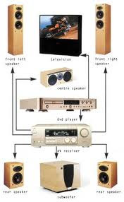
Off to the basics, the first thing you’ll need when creating a home theater for your family to enjoy is a television. It might seem a little too obvious to some but I have yet to find a box kit that includes a television—mainly because the choice of screen is for many the most personal aspect of selecting a home theater. There are essentially three choices in today’s television market: front projector, rear projector, and plasma. There are variations within each of these and the prices fall anywhere from modest to quite costly. This is the component that most home theater owners spend the most time contemplating and it affects the types of components that will be most effective later on in terms of things such as high definition and other choices you can make.

A receiver is another important component. You will probably have a DVD player or recorder of some sort as part of your system; you may have a Tivo and cable box or satellite and will probably have speakers of some sort for your system. The receiver is the box you plug them all into—it receives all of this inputs and correlates it so to speak. This is the ultimate traffic director when it comes to your home theater and I suggest you spend a good portion of your home theater budget making sure that this is a good quality part.

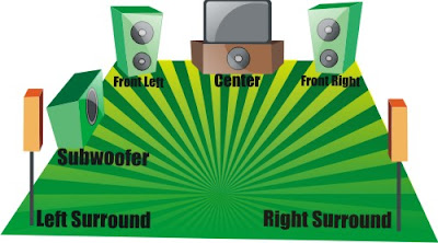
Speakers are where your sound will flow. One of the best things to me about a home theater is the ability to experience surround sound very similar to what I experience in theaters while having the ability to put my feet up or snuggle under blankets (which simply can’t be achieved in a theater). Speakers come in all shapes and sizes and are also quite personal for some consumers while give and take for others. You can purchase these are part of a kit in order to make the selection process easier.

Finally, you have your DVD player or recorder. If high definition is important to you, you now have that option. If your television isn’t HD ready or capable, I’d pass and go for an older (less expensive) model of DVD player until something more up-to-date is called for. These items are a great start for any home theater and you can build, expand, and upgrade over time for an even better system. Enjoy!

PPPPP

599

Related Circuit : Make 5.1 channel amplifier and speaker setup
Read More..

Thursday, November 28, 2013

Power Amplifier for Audio Laptop

Frequently, the sound yield from a laptops fabricated-in speakers is flat. A capacity intensifier is needed to get an elevated volume. Here is an effortless circuit to intensify the laptops sound yield. 
The circuit is constructed around capacity enhancer IC LA 4440 (IC1) and a few alternate parts. LA4440 is a double channel sound capacity speaker. It has level twisting over a vast run of flat to towering frequencies with exceptional channel detachment. Inbuilt double channels prepare it for stereo and extension speaker provisions.
image : http://circuitschematicelectronics.blogspot.com/2011/02/2-x-20-watt-car-amplifier.html

In double mode LA4440 gives 6 watts for every divert and in scaffold mode 19-watt yield. It has swell denial of 46 dB. The sound impact might be grasped by utilizing several 6-watt speakers. Associate binds 2, 6 and ground of IC1 to the stereo jack which is to be utilized with the laptop. Collect the circuit on a customary-reason PCB and encase in a suitable bureau. The circuit works off managed 12V capacity supply. It is suggested to utilize sound enter socket in the circuit plank. Utilize a decent hotness-sink for LA4440.
Read More..