Showing posts with label components. Show all posts

Friday, October 24, 2014

Battery Discharger Using Discrete Components

The battery discharger published in this website may be improved by adding a Schottky diode (D3). This ensures that a NiCd cell is discharged not to 0.6–0.7 V, but to just under 1 V as recommended by the manufacturers. An additional effect is then that light-emitting diode D2 flashes when the battery connected to the terminals is flat. The circuit in the diagram is based on an astable multivibrator operating at a frequency of about 25 kHz. When transistor T2 conducts, a current flows through inductor L1, whereupon energy is stored in the resulting electromagnetic field. When T2 is cut off, the field collapses, whereupon a counter-emf is produced at a level that exceeds the forward voltage (about 1.6 V) of D2.

Battery Discharger Circuit Diagram0

A current then flows through the diode so that this lights. Diode D1 prevents the current flowing through R4 and C2. This process is halted only when the battery voltage no longer provides a sufficient base potential for the transistors. In the original circuit, this happened at about 0.65 V. The addition of the forward bias of D3 (about 0.3 V), the final discharge voltage of the battery is raised to 0.9–1.0 V. Additional resistors R5 and R6 ensure that sufficient current flows through D3. When the battery is discharged to the recommended level, it must be removed from the discharger since, in contrast to the original circuit, a small current continues to flow through D3, R2-R3, and R5-R6 until the battery is totally discharged.

The flashing of D2 when the battery is nearing recommended discharge is caused by the increasing internal resistance of the battery lowering the terminal voltage to below the threshold level. If no current flows, the internal resistance is of no consequence since the terminal voltage rises to the threshold voltage by taking some energy from the battery. When the discharge is complete to the recommended level, the LED goes out. It should therefore be noted that the battery is discharged sufficiently when the LED begins to flash.


http://www.ecircuitslab.com/
Read More..

Thursday, September 18, 2014

HQ Notch Filter Without Close Tolerance Components

A notch for a narrow frequency band of a few per cent or even less normally requires close-tolerance components. At least, that’s what we thought until we came across a special opamp IC from Maxim. In filters with steep slopes, the component tolerances will interact in the complex frequency response. This effect rules out the use of standard tolerance components if any useful result is to be achieved. The circuit shown here relocates the issue of the value-sensitive resistors that determine the filter response from ‘visible’ resistors to ready available integrated circuits which also make the PCB layout for the filter much simpler. The operational amplifiers we’ve in mind contain laser-trimmed resistors that maintain their nominal value within 1‰ or less. For the same accuracy, the effort that goes into matching individual precision resistors would be far more costly and time consuming. The desired notch (rejection) frequency is easily calculated for both R-C sections shown in Figure 1.
High-Q_Notch_filter-circuit-diagramw
Figure 1. Special opamps incorporating laser-trimmed resistors.
Dividing the workload:
The circuit separates the amplitude and frequency domains using two frequency-determining R-C networks and two level-determining feedback networks of summing amplifier IC2, which suppresses the frequency component to be eliminated from the input signal by simple phase shifting. IC1 contains two operational amplifiers complete with a feedback network. The MAX4075 is available in no fewer than 54 different gain specifications ranging from 0.25 V/V to 100 V/V, or +1.25 V/V to 101 V/V when non-inverting. The suffix AD indicates that we are employing the inverting version here (G = –1). These ICs operate as all-pass filters producing a phase shift of exactly 180 degrees at the roll-off frequency f0. The integrated amplifier resistors can be trusted to introduce a gain variation of less than 0.1 %.
They are responsible for the signal level (at the notch frequency) which is added to the input signal by IC2 by a summing operation. However, they do not affect the notch frequency proper — that is the domain of the two external R-C sections which, in turn, do not affect the degree of signal suppression. In general, SMDs (surface mount devices) have smaller production tolerance than their leaded counter-parts. Because the two ICs in this circuit are only available in an 8-pin SOIC enclosure anyway, it seems logical to employ SMDs in the rest of the circuit as well. Preset P1 allows the filter to be adjusted for maximum rejection of the unwanted frequency component.
High_Q_Notch_filter-circuit-diagram1
Figure 2. This deep notch is within reach using just 5%-tolerance resistors and 20%-tolerance capacitors.

R-C notch filter:
Using standard-tolerance resistors for R1 and R2 (i.e., 1%, 0806 style) and 10%-tolerance capacitors for C1 and C2 (X7R ceramic) an amount of rejection better than that shown in Figure 2 may be achieved. The notch frequency proper may be defined more accurately by the use of selected R-C sections. Pin 3 of IC2 receives a signal that’s been 90-degrees phase shifted twice at the notch frequency, while pin 1 is fed with the input signal. These two signals are added by way of the two on-chip resistors. IC2 is a differential precision operational amplifier containing precision resistor networks trimmed to an error not exceeding ±0.2‰. Here, it is configured as a modified summing amplifier with its inverting input, pin 2, left open.

Table_High-Q_Notch_filter-circuit-diagramt

For frequencies considerably lower than the resonance frequency f0 = 1 / (2 π R C) the capacitors present a high impedance, preventing the inverting voltage followers from phase-shifting the signal. At higher frequencies than f0, each inverting voltage follower shifts its input signal by 180 degrees, producing a total shift of 360 degrees which (electrically) equals 0 degrees. The phases of each all-pass filter behave like a simple R-C pole, hence shift the signal at the resonance frequency by 90 degrees each. The three precision amplifier ICs can handle signals up to 100 kHz at remarkably low distortion. The supply voltage may be anything between 2.7 V and 5.5V. Current consumption will be of the order of 250µA.
Source :www.ecircuitslab.com
Read More..

Tuesday, December 17, 2013

Basic Components for a Home Theater

Many people never bother looking into purchasing a home theater through sheer fear of the decisions that may need to be made in the process. Many among these aren’t even sure of exactly which components are included in a home theater or which ones are needed in order to create an effective and entertaining home theater. For this reason, many people simply do not bother going through the process of looking at their options when it comes to these wonderful systems on the market today much less ever bother actually purchasing one.

Basic Components for a Home Theater
If you are one of the many who has experienced some degree of confusion when it comes to the individual parts and pieces that are included in a home theater system and what they do, hopefully you will gain a better understanding once you’ve finished reading. The first thing to understand is that there are varying degrees when it comes to home theaters. The following components are the makings of a very basic home theater that will provide excellent functionality. They are not however inclusive of every possible piece or part that could make up a home theater system.

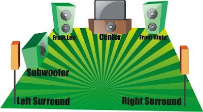
Speaker Setup
Speaker Setup
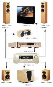
Off to the basics, the first thing you’ll need when creating a home theater for your family to enjoy is a television. It might seem a little too obvious to some but I have yet to find a box kit that includes a television—mainly because the choice of screen is for many the most personal aspect of selecting a home theater. There are essentially three choices in today’s television market: front projector, rear projector, and plasma. There are variations within each of these and the prices fall anywhere from modest to quite costly. This is the component that most home theater owners spend the most time contemplating and it affects the types of components that will be most effective later on in terms of things such as high definition and other choices you can make.

A receiver is another important component. You will probably have a DVD player or recorder of some sort as part of your system; you may have a Tivo and cable box or satellite and will probably have speakers of some sort for your system. The receiver is the box you plug them all into—it receives all of this inputs and correlates it so to speak. This is the ultimate traffic director when it comes to your home theater and I suggest you spend a good portion of your home theater budget making sure that this is a good quality part.

Speakers are where your sound will flow. One of the best things to me about a home theater is the ability to experience surround sound very similar to what I experience in theaters while having the ability to put my feet up or snuggle under blankets (which simply can’t be achieved in a theater). Speakers come in all shapes and sizes and are also quite personal for some consumers while give and take for others. You can purchase these are part of a kit in order to make the selection process easier.

Finally, you have your DVD player or recorder. If high definition is important to you, you now have that option. If your television isn’t HD ready or capable, I’d pass and go for an older (less expensive) model of DVD player until something more up-to-date is called for. These items are a great start for any home theater and you can build, expand, and upgrade over time for an even better system. Enjoy!

PPPPP

599

Related Circuit : Make 5.1 channel amplifier and speaker setup
Read More..