Showing posts with label watt. Show all posts
Showing posts with label watt. Show all posts
Sunday, February 9, 2014
10 Watt Power Amplifier Circuit
IC BA514 its the main of this circuit. This is actually low power output with minimum power output 2 W but maximum output 10W . Minimum voltage require 9 Volt and maximum voltage 14 Volt . Impedance output 4 Ohm.Power Amplifier Schematic below :
 |
| Click to view Larger |
All capacitor with uF and minimum voltage capacitor is 16 V. resistor with 1/4 Watt.

Thursday, December 26, 2013
600 Watt Quasi Amplifier With Mosfet IRFP460
ACTK 400/600 Watt
Two versions of a robust module capable of delivering high powwer for extended periods. The Actrk400 uses 6 n-channel Mosfets in the output stage to deliver around 400 watts into 4 ohms while the Actrk600 uses 12 n-channel Mosfets in the output stage to deliver power in excess of 600 watts into 4 ohms. One constructor has achieved almost 900 watts with the Actrk600 layout using 12 IRFP460 Mosfets.
 |
| 600 Watt Quasi Amplifier With Mosfet IRFP460 |
Wednesday, December 25, 2013
Gambar Skema Rangkain Audio Amplifier 10 Watt
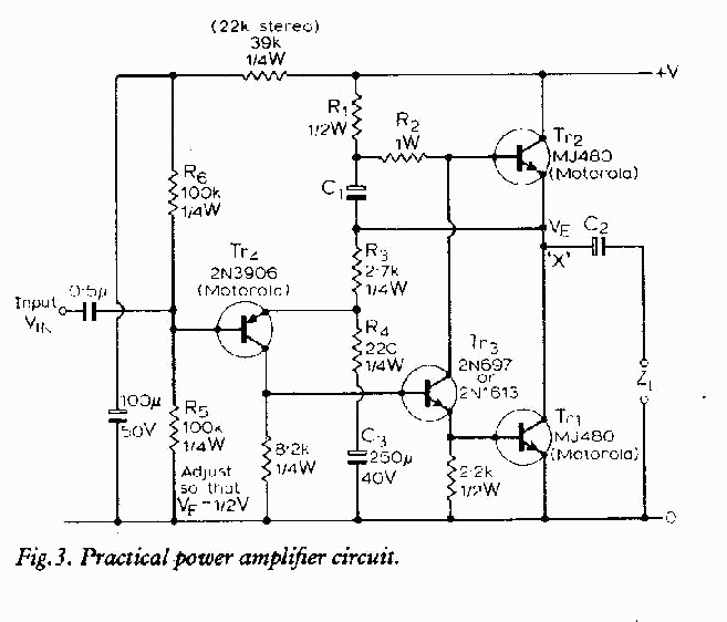 Gambar Skema Rangkain Audio Amplifier 10 Watt
This schematic is a 10 watt amplifier for audio frequencies (approx. 50Hz-20kHz). The circuit is extremely simple, comprised of a total of only 18 components, 4 of which are transistors. Of the transistors used, 1 is a PNP (2N3906) , and 3 are NPN (2n697, 2 x NJ480).
Source : www.electrokits.com
Source : www.electrokits.com
Tuesday, December 24, 2013
230 400 Watt Power Amplifier MOSFET
Amplifier circuit below is a series of amplifiers with the amplifier transistor and mosfet. This amplifier output power ranging from 230W up to 400W.
 |
| 230 - 400 Watt Power Amplifier |
Saturday, December 21, 2013
Regulated 24 Watt Broad Spectrum LED Lamp
This project involves constructing an energy efficient broad spectrum LED lamp system. The lamp is useful for indoor reflective room lighting. It has a broad color spectrum that more closely approximates the light of the sun when compared to fluorescent bulbs and white-only LEDs. The light level is regulated and the light that is produced does not flicker. The six differently colored LED stars, made by LedEngin, Inc., are rated at 5 watts (nominal). The LED array and associated current regulator consume 1 amp at 24VDC (24 Watts). NEVER stare directly at this lamp when it is running at full operating power, it is DANGEROUSLY BRIGHT.

With the LEDs shown, the combined color of the lamp has a pinkish white hue. The 5 Watt ratings of the LEDs are not precise, the white, blue and green LEDs consume about 4W and the lower voltage red, orange and deep red LEDs consume about 3W. The current regulator keeps the LED brightness constant and insures that the LED series string never draws more than 1 amp of current.
The project has also been coined "Bold as LED" in reference to the Jimi Hendrix song "Bold as Love" which has the lyric: "My yellow in this case is not so mellow".
Specs:
The lamp is wired as a current loop which includes the power supply, the LED series string and the 1 amp current regulator circuit. The LM317K and 1.2 ohm 5 Watt resistor act as a current regulator that limits the loop current to 1 Amp. During regulation, there will always be 1.2V across the 1.2 ohm resistor. The current regulator insures that the LEDs always run at their maximum brightness, but not so bright that they burn out. A 100uF electrolytic capacitor bypasses the DC power input to the device and a 100nF monoblock capacitor bypasses the LM317K input.
Construction:
The LEDs and current regulator circuit were mounted on a 3" x 8" chunk of 1/8" aluminum stock. The LM317K regulator and LED heat sinks were bolted to the chassis directly, heat sink grease was used on the regulator, the heat sinks and the six LEDs. Connecting the LM317K directly to the aluminum plate makes the plate electrically hot at 1.2V, the plate should not be allowed to come into contact with any live conductors. By using a few more parts, the LM317 can be mounted with an insulator and plastic shoulder washers for electrical isolation from the mounting plate.
The LEDs come mounted on their own small star-shaped aluminum substrates, these were attached to the aluminum plate using two 7/16" 4-40 screws and nuts per LED. A drop of silicone heat sink grease should be applied to the center of each LED star when it is mounted to the plate for heat conduction. It is important to use insulating plastic washers on the top side of the LED stars to prevent electrical contact with head of the screw. The LED stars were soldered together using short pieces of #20 tinned wire after being mounted on the plate. It is necessary to use a fair amount of heat to solder the contacts, a 200/240W soldering gun did the job. Be very careful not to melt the lenses on the LEDs, the LEDs cost around $10 each. The positive and negative leads of the LED series string were connected back to the current reglator circuitry using #20 wire covered with teflon insulation.
The initial mechanical arrangement did not pass the "rule of thumb" test, which says that if a semiconductor is too hot to hold your thumb on, it will not live a long life. Two large aluminum heat sinks were bolted to the back of the aluminum plate and seem to be sufficient to keep the lamp operating at a reasonable temperature. The LED array produces more heat than the LM317K.
Use:
Connect this circuit to a 24VDC power supply or other power source such as a solar-charged lead acid battery. Be sure to observe the correct polarity. Look away from the LEDs and apply power. Again, do not stare directly at the LEDs, they are bright enough to harm your vision. A switch-mode power supply rated at 24VDC and 1 Amp or more is probably the most energy-efficient way to power this device from line power.
Parts:
1x LM317K T03 case 1.5A adjustable voltage regulator
1x 1.2 ohm 5W resistor (or 2x 2.4 ohm 2W resistors in parallel)
1x 100uF 35V or higher electrolytic capacitor
1x 100nF 35V or higher monolythic capacitor
1x LedEngin LZ1-10R205 deep red 5W LED
1x LedEngin LZ1-10R105 red 5W LED
1x LedEngin LZ1-10A105 amber 5W LED
1x LedEngin LZ1-10G105 green 5W LED
1x LedEngin LZ1-10B105 blue 5W LED
1x LedEngin LZ1-10CW05 cool white 5W LED
Miscellaneous wire, solder lugs, termination strips and hardware,
Large aluminum mounting plate, heat sinks if necessary.
With the LEDs shown, the combined color of the lamp has a pinkish white hue. The 5 Watt ratings of the LEDs are not precise, the white, blue and green LEDs consume about 4W and the lower voltage red, orange and deep red LEDs consume about 3W. The current regulator keeps the LED brightness constant and insures that the LED series string never draws more than 1 amp of current.
The project has also been coined "Bold as LED" in reference to the Jimi Hendrix song "Bold as Love" which has the lyric: "My yellow in this case is not so mellow".
Specs:
- Nominal operating power: 24 Watts (24V DC at 1 Amp)
- LED power consumption above regulation point: 18.6 Watts
- Maximum operating voltage: 28V DC
- Minimum voltage for regulated light: 23V DC
- Leds produce light down to 11V
- Deep Red LED voltage: 2.55V
- Red LED voltage: 2.37V
- Amber LED voltage: 2.60V
- Green LED voltage: 3.92V
- Blue LED voltage: 3.56V
- White LED voltage: 3.7V
- Voltage across regulator when current becomes regulated: 4.2V
The lamp is wired as a current loop which includes the power supply, the LED series string and the 1 amp current regulator circuit. The LM317K and 1.2 ohm 5 Watt resistor act as a current regulator that limits the loop current to 1 Amp. During regulation, there will always be 1.2V across the 1.2 ohm resistor. The current regulator insures that the LEDs always run at their maximum brightness, but not so bright that they burn out. A 100uF electrolytic capacitor bypasses the DC power input to the device and a 100nF monoblock capacitor bypasses the LM317K input.
Construction:
The LEDs and current regulator circuit were mounted on a 3" x 8" chunk of 1/8" aluminum stock. The LM317K regulator and LED heat sinks were bolted to the chassis directly, heat sink grease was used on the regulator, the heat sinks and the six LEDs. Connecting the LM317K directly to the aluminum plate makes the plate electrically hot at 1.2V, the plate should not be allowed to come into contact with any live conductors. By using a few more parts, the LM317 can be mounted with an insulator and plastic shoulder washers for electrical isolation from the mounting plate.
The LEDs come mounted on their own small star-shaped aluminum substrates, these were attached to the aluminum plate using two 7/16" 4-40 screws and nuts per LED. A drop of silicone heat sink grease should be applied to the center of each LED star when it is mounted to the plate for heat conduction. It is important to use insulating plastic washers on the top side of the LED stars to prevent electrical contact with head of the screw. The LED stars were soldered together using short pieces of #20 tinned wire after being mounted on the plate. It is necessary to use a fair amount of heat to solder the contacts, a 200/240W soldering gun did the job. Be very careful not to melt the lenses on the LEDs, the LEDs cost around $10 each. The positive and negative leads of the LED series string were connected back to the current reglator circuitry using #20 wire covered with teflon insulation.
The initial mechanical arrangement did not pass the "rule of thumb" test, which says that if a semiconductor is too hot to hold your thumb on, it will not live a long life. Two large aluminum heat sinks were bolted to the back of the aluminum plate and seem to be sufficient to keep the lamp operating at a reasonable temperature. The LED array produces more heat than the LM317K.
Use:
Connect this circuit to a 24VDC power supply or other power source such as a solar-charged lead acid battery. Be sure to observe the correct polarity. Look away from the LEDs and apply power. Again, do not stare directly at the LEDs, they are bright enough to harm your vision. A switch-mode power supply rated at 24VDC and 1 Amp or more is probably the most energy-efficient way to power this device from line power.
Parts:
1x LM317K T03 case 1.5A adjustable voltage regulator
1x 1.2 ohm 5W resistor (or 2x 2.4 ohm 2W resistors in parallel)
1x 100uF 35V or higher electrolytic capacitor
1x 100nF 35V or higher monolythic capacitor
1x LedEngin LZ1-10R205 deep red 5W LED
1x LedEngin LZ1-10R105 red 5W LED
1x LedEngin LZ1-10A105 amber 5W LED
1x LedEngin LZ1-10G105 green 5W LED
1x LedEngin LZ1-10B105 blue 5W LED
1x LedEngin LZ1-10CW05 cool white 5W LED
Miscellaneous wire, solder lugs, termination strips and hardware,
Large aluminum mounting plate, heat sinks if necessary.
Friday, December 13, 2013
2 X 2 4 2 x 4 5 17 Watt Power Amplifier
Amplifier circuit here is all based on the ic in the gains. Three IC TA7230P, TA7236P, TA7237AP is intregated circuit (IC) which was applied to the power amplifier. Each IC has a different output, different input voltage, all IC TA7230P, TA7236P, TA7237AP is manufactured by Toshiba.
Read More..
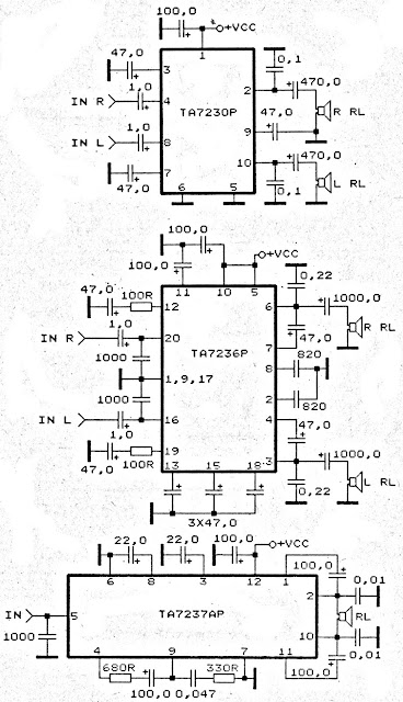 |
TA7230P, TA7236P, TA7237AP amplifier schematic |
Tuesday, December 10, 2013
Inverter 5000 Watt PWM
This inverter uses PWM (Pulse Width Modulator) with type IC SG3524. IC serves as a oscillator 50Hz, as a regulator of the desired output voltage. Input power ranging from 250W up to 5000W output and has. Following a series INVERTER 5000W with PWM (Pulse Width Modulator).
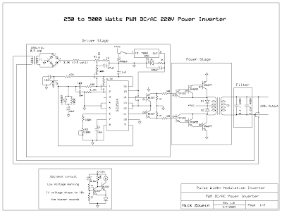 |
| Schematic Inverter 5000W with PWM (Pulse Width Modulator) |
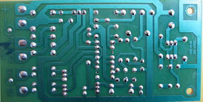 |
| Layout PCB Inverter 5000W with PWM (Pulse Width Modulator) |
below is the output power settings that can be issued by this inverter:
DC voltage and Transformer "T2" winding recommendation:
Winding Power Supply
12VDC 750W P: 24V "12-0-12" / S: 220V
1500W 24VDC P: 48V "24-0-24" / S: 220V
2250w 36VDC P: 72V "36-0-36" / S: 220V
3000w 48VDC P: 96V "48-0-48" / S: 220V
3750w 60VDC P: 120V "60-0-60" / S: 220V
4500w 72VDC P: 144V "72-0-72" / S: 220V
5250w 84VDC P: 168V "84-0-84" / S: 220V
Transformer used is the transformer CT
R1 serves to regulate the voltage to 220v inverter
R2 serves to regulate the inverter output frequency of 50 or 60 Hz (as appropriate)
90 Watt Switching Power Supply

Switching Power Supply in this article are able to supply power 90 Watt. Switching Power Supply series is built directly from an AC network system using special IC MC33374 switching power supply in the form of High Voltage Power Switching Regulator and with external components to the other.
IC MC33374 IC is a switching power supply designed to operate with an AC voltage source and works as a power switching converter with flyback technique. Switching Power Supply Series has a 15 volt DC output with current up to 6 Ampere.
IC MC33374 IC is a switching power supply designed to operate with an AC voltage source and works as a power switching converter with flyback technique. Switching Power Supply Series has a 15 volt DC output with current up to 6 Ampere.
 |
| 90 Watt Switching Power Supply Schematic |
Series 90 Watt Switching Power Supply works by menyearahkan AC source is then used to activate the converter MC33374 system. The output of transformer switching converter MC33374 searahkan again later on as a DC voltage supply to be used for electronic devices.
Friday, December 6, 2013
TDA2005 2 X 20 Watt Power Amplifier
This time, there is a series of audio amplifer 20W as well, but using IC TDA 2005 as a series of his base amplifier.
The series of 2x20 Watt Audio Power Amplifier using TDA2005 can you see in the picture below.
The series of 2x20 Watt Audio Power Amplifier using TDA2005 can you see in the picture below.
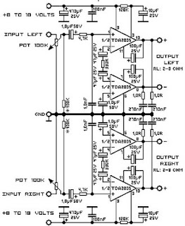
Technical Data:
Performance of TDA2005M: (for this circuit); At 4.14 V supply voltage: 2 x 20 watts (stereo) into 4 Ohms.
Distortion: Approx. 0.2% at 4 Watts into 4 ohm load.Frequency Range: Approx. 20 Hz to 22 KHz.
Input Sensitivity: Approx. maximum 150 mV rms. .
Power supply: + 8 to 18 volts, approx. 3.5 Amps maximum per channel.
Wednesday, November 27, 2013
2 X 1 8 Watt stereo low power amplifier circuit
This is Low power amplifier , based on IC TDA2824 product of Philips. Maximum output is about 2 X 1,8 Watt , these include low output amplifier type. Minimum required voltage 3 Volts and maximum voltage of 18 volts DC.

Spec :
- Supply Voltage : 3 - 18 Volts
- Power Output : 2 x 1,3 Watts
- RL impedance : 4 Ohms
- Frequency responses : 30Hz -18kHz
- Quiescent current : 6 mA
Sunday, November 24, 2013
Mosfet Power Amplifier 100 Watt
At this time a unsophisticated MOSFET amplifier or else power Amp which Output power is plus/minus 100 Watt/RMS with 8 Ohms otherwise ohter plus/minus 160 Watts /RMS with 4 ohms.
 |
| Mosfet Amplifier 100 Watt RMS |
Regarding this circuit simplicity, The distortion is plus/minus 0.1 %. In support of mob-width -3 db(decibel) is increase for 4 Hz to 96 Khz, it is narrow by C1, R1, C2 and R2. Taking part in the two transistors are T1 and T2 makes a initial differential stage part, So,current source(I) of +/- solitary mA is put with resistor R3. In favor of the upgraded project, The current source(I) is new efficient in stability. Coil P1 allows a fine tuning of dictate current voltage on amplifier’s output. Place the Coil P1 with it’s partially usefulness in favor of first power up, so therefore break it unhurriedly for a lowest DC output voltage. custom a essential quality compoment.
Electronic Part
C1 = 2,2 µF MKP, MKT 100 in opposition to
C2 = 330 pF céramique 50 V
C3 = 100 nF MKP, MKT 100 in opposition to
C4 = 100 µF 40 V électro-chimique
C5, C6 = 18 pF céramique 50 vs.
C7 = 100 nF MKP, MKT 250 V (C8 = 47 µF 100 V)
R1, R3 = 47 K (R3 = 330 -> 470 Ohms)
R2 = 2K2
R4, R5 = 3K9
R6 = 1 K
R7 = 27 K
R8, R9, R11 = 100 ohms
R10 = 10 K
R12, R13 = 470 ohms
R14, R15 = 0.33 ohms 5 watts
R16 = 10 ohms 3 watts (R17 = 1 K R18, R19 = 10K)
T1, T2, T9,T10 = 2SD756A,2SD716A, BC556B (attention au brochage différent - take be concerned representing pin arrange)
T7 = IRFP240, 2SK1530, 2SJ162, BUZ900DP, BUZ901DP (attention au brochage dissimilar - take care for pin layout : GDS GSD)P1 = 100 ohms (25 turns - 25 turns)
Subscribe to:
Posts (Atom)