Showing posts with label stereo. Show all posts
Showing posts with label stereo. Show all posts
Thursday, February 6, 2014
Stereo Balance Indicator
This stereo balance indicator circuit diagram is designed using few common external components .The schematic circuit is very simple to build and will provide an visual indication with LEDs for left , right and center balance .
Stereo Balance Indicator Circuit Diagram

Outputs from each channel are fed to the two inputs of IC1 connected as a differential amplifier . Output of the IC1 is connected to the noninverting inputs of the IC2 and IC3 . If the outputs of the IC1 approaches the supply rail , the outputs of the IC2 and IC3 will go high illuminating the LED 3 , this will show that the right channel is dominating . If the sound is balanced to the left channel , the Ic2 and IC3 will go low and the LED1 will light . If both channels are equal in amplitude the outputs of the IC2 and IC3 would be low and high respectively , lighting up LED2 .

Sunday, December 22, 2013
Combine stereo input to one output
Here , I will give a circuit of schemes that are used to combine 2 pieces input or stereo to 1 input mono. Why 2 inputs in to one because, if we need a stereo amplifier we want to become a stronger by combining the two input into one input, so that a higher power output. Actually without any circuit above we can combine stereo amplifier into mono, but the sound output less than the maximum , need for this additional combiner circuit.

R1______150K
R2______920R
R3______150K
R4______920R
R5______920R
U1______NE5532
For balance _: R1 / R2=R3 / R4
For balance _: R1 = R3
Gain ______: R5 / R1 = R5 / R3
Wednesday, December 11, 2013
Stereo TDA2822 audio power amplifier circuit

In this series I use IC tda2822M as the main amplifier, but if you want to use in addition to IC TDA2822M you can use ic I mentioned this is KA2209, NJM2073, U2822B, U2823B. Output is issued no more than 4W, which had low output. Supply voltage from 3 volts to 16 volts.
Below its schematics of TDA2822 stereo audio power amplifier

R1 = 4.7R
R2 = 4.7R
C1 = 1uF
C2 = 100uF
C3 = 100uF
C4 = 0.1uF
C5 = 470uF
C6 = 1uF
C7 = 100uF
C8 = 0.1uF
C7 = 100uF
C8 = 0.1uF
C9 = 470uF
ICs = KA2209 , NJM2073 , TDA2822 , U2822B , U2823B
Thursday, December 5, 2013
Stereo Balance Indicator
Mechanical deficiencies that affect the reproduction of sound in a stereo amplifier is probably what you are thinking, armpit all the problems have been overcome. And actually bigger role than we know. True, the effect is so small that only a few of us who record it, or divert it to other things.
Most of such shortcomings can be traced back toto the stereo volume control ,maybe two in the no -stepresistance . As a result, the volume difference arises between the two channels and can usually be in balance again by the regulator balance. If you intend to define these differences precisely, stereo balance these indicators can fulfill your purpose.
 |
| Stereo Balance Indicator circuit |
Quite simply, this circuit by connecting the output terminal and the right channel loudspeaker left channel of the amplifier and feed the same signal, should sinusoid (or cues mono) to the second input channel amplifier. If then the signals at both terminals tarafnya exact same loudspeakers, meters (zero in the middle) in the indicator of this balance will not deviate. However, if the signal level in the left channel is higher than the right channel meter will deviate to the left (or right if the opposite occurs). In this regulatory balance can be set up to read something about zero feet again, then the effect of volume control tracking error can be eliminated.
Trimpot P1 on balance the indicator should be set for full scale meter deflection, when only one channel worked.
Tuesday, December 3, 2013
Stereo 9 Volt power amplifier circuit
Here I will explain about the necessary voltage and power amplifier output. The voltage should have at least approximately 9Volt 30Volt voltage and maximum voltage on the DC current. For maximum output of 2 X 2Watt with impedance 8-16 ohm. Because this amplifier circuit using ic and ic is used have the equation, so that if used different ic, then the required output voltage and also differ depending ic respectively.

Part List :
Resistor
R1 = 1M
R2 = 1M
R3 = 1K
R4 = 1K
R5 = 100K
R6 = 100K
R7 = 1R
R8 = 1R
Capacitor
C1 = 1uF
C2 = 220uF
C3 = 1uF
C4 = 100uF
C5 = 5uF
C6 = 5uF
C7 = 0.1uF
C8 = 220uF
C9 = 220uF
C10 = 0.1uF
IC
U1 = ULN2274B , ULN2277 , ULN2278B
Monday, December 2, 2013
Stereo STK013 audio amplifier circuit

On the amplifier circuit using ic STK, the same as my previous posting. However, in the above circuit has 2 inputs and 2 outputs, or commonly called a stereo amplifier. This issue of power amplifier 2 x 18Watt and has impedance 8. To stress that it takes about 35-38Volt.Component list :
Resistor
R1 = 390K
R2 = 390K
R3 = 220K
R4 = 220K
R5 = 220K
R6 = 220K
R7 = 100R
R8 = 1R
R9 = 9.1K
R10 = 9.1K
R11 = 1R
Capacitor
C1 = 10uF
C2 = 10uF
C3 = 0.47uF
C4 = 0.47uF
C5 = 220uF
C6 = 0.047uF
C7 = 4700uF
C8 = 100uF
C9 = 1000uF
C10 = 100uF
C11 = 4700uF
C12 = 470uF
C13 = 0.047uF
IC
U1 = STK013
Wednesday, November 27, 2013
2 X 1 8 Watt stereo low power amplifier circuit
This is Low power amplifier , based on IC TDA2824 product of Philips. Maximum output is about 2 X 1,8 Watt , these include low output amplifier type. Minimum required voltage 3 Volts and maximum voltage of 18 volts DC.

Spec :
- Supply Voltage : 3 - 18 Volts
- Power Output : 2 x 1,3 Watts
- RL impedance : 4 Ohms
- Frequency responses : 30Hz -18kHz
- Quiescent current : 6 mA
Tuesday, November 26, 2013
BA5406 10W Stereo Power Amplifier
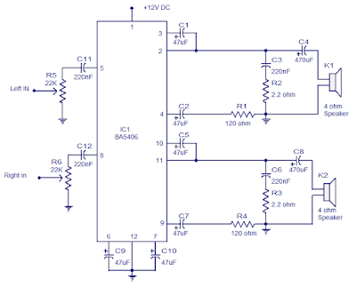
BA5406 is a monolithic integrated stereo amplifier from ROHM semiconductors. It can transfer 5W apiece channel into a 4 ohm loudspeaker by the side of 9V supply. Amplifiers based on BA5406 does not require an output coupling transformer and can subsist operated from a single supply. The operating voltage range is from 5 to 15V DC. This makes the IC correct in lieu of low power car audio applications. Other applications of BA5406 are portable audio players, stereo module systems, television and all that. The BA5406 has important channel separation, excellent channel isolation, unimportant pop-up clatter, low noise, low thermal resistance and is open arrived a 12 pin SIP package.
 |
| BA5406 10 Watt Stereo Power Amplifier |
In the circuit diagram revealed lower, BA5406 is configures to hand over 5×2 watts into 4 ohm loudspeakers by the side of a supply voltage of 9 volts. Capacitor C3 is a power supply filter capacitor. C11 and C12 are input DC decoupling capacitors on behalf of the missing and due channels. C3 and R2 forms a Zobel arrangement for the not here output while C6 & R3 forms the same for the right channel. single-mindedness of the Zobel network is to reduce oscillations and rally in height frequency stability of the amplifier. Potentiometers R5 and R6 serves since the volume control on behalf of the not here and right channels. CapacitorsC4 and C8 pair the outputs of the amplifier to the speakers. C9 and C10 are clamor filtering capacitors. C1 and C5 are bootstrap capacitors for the not here and right channels.
Subscribe to:
Posts (Atom)