Showing posts with label remote. Show all posts

Thursday, February 27, 2014

Remote Audio Level Indicator

The normal level-indicator circuits which are available in the market require connections to be made to the output of the player, which may not be easily accessible. The audio level indicator circuit described here removes this restriction as it may be placed close to the player’s speakers and yet the desired effect can be realised. 

Circuit diagram :
Remote Audio Level Indicator-Circuit Diagram
Remote Audio Level Indicator Circuit Diagram

As shown in the circuit, signals are picked up by the condenser microphone, which get further amplified by the noninverting amplifier built around one of the four op-amps of LM324. The remaining three, along with four op-amps of the second LM324, are used as seven comparators to work as the level detector, giving seven output levels through seven coloured LEDs. 

The sensitivity of the audio level indicator circuit may be improved by varying the 220k potentiometer. If a fine adjustment is desired, a 4.7-kilohm potentiometer may be connected in series resistors with the 220k potentiometer.


Copyright : EFY
Read More..

Sunday, December 15, 2013

Infrared Remote Control Tester


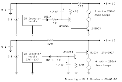
This is a fairly easy circuit that can be used to test TV and VCR remote controls. The infrared detector module (GP1U52X) (Radio Shack 276-137) produces a 5 volt TTL pulse train corresponding to the digital code of the particular remote control key pressed. In the lower circuit, the module output is normally low with no signal received and becomes a positive going pulse train when a signal is present. Other detector modules are available that have an inverted output as shown in the upper drawing which is the type I used, but I dont have the part number, I believe it was removed from a VCR. 

Infrared Remote Control Tester

The pulse sequence represents the digital code of the particular key pressed along with possible manufacturer information. As the pulse train occurs, the 4.7uF capacitor is charged to about 3 volts and the capacitor voltage minus a diode drop appears across the 470 ohm resistor yielding a collector current from the 2N3904 or 2N3906 of about 5 milliamps. The collector current of the first stage flows into the base of the output transistor (MJE34 or 2N3053) which delivers around 250 mA into the indicator lamps. When the pulse train ends, the capacitor slowly discharges through the base of the first stage transistor allowing the Xmas tree lights to remain on for a about 1 second. The little Xmas lamps will operate over a wide voltage range, so you can use bulbs from almost any string, but bulbs from shorter strings (35 or less) will probably last longer operated at 5 volts.

The circuit can be powered from a small 9-12 volt DC, 250 mA or greater wall transformer. It may also need an additional 1000 uF filter capacitor across the DC output if the wall transformer does not have a built in capacitor. For use with a 9 volt battery, the incandescent lamps can be replaced with a regular LED and 680 ohm resistor and the output transistors can be replaced with small signal transistors (2N3904 or 2N3906). The total current drain will be about 25 mA with the LED lit, and 15 mA standby when the LED is off.
Read More..

Monday, November 25, 2013

TV Remote Tester Circuit

The circuit is very effective to test the remote controls what still works or not, the remote record will be tested using infra red. Examples of the TV remote, AC and others. Please try I am sure 100% will be successful.


TV Remote Tester Circuit
TV  Remote Tester Circuit

The workings of the circuit is very simple, when the infra red sensor receive infrared signals pin 2 sensor will produce a voltage, this voltage will drives the PNP transistor so that the LED lamp and piezo disc (BZ) is active. for the power supply you can use a 9 volt battery and then use IC 7805 or use 1.5 volt batteries x 3

Following the specification of components installed
Transistor BC557
TSOP 1738 Sensor Infra Red
R1 = 10k ohm ¼ watt Resistor
R2 = 1k ohm ¼ watt Resistor
R3 = 1k ohm ¼ watt Resistor
BZ = piezo disc
led
Read More..