Showing posts with label control. Show all posts
Showing posts with label control. Show all posts
Friday, February 7, 2014
Alternating ON OFF Control
Use this circuit instead of a standard on-off switch. Switching is very gentle. Connect unused input pins
to an appropriate logic level. Unused output pins *MUST* be left open!. First push switches ON,
another push switches OFF. You can use 1/4 watt resistors if they are metal-film type. Any proper
substitute will work for Q1, including the european TUNs. For C2, if you find the relay acts not fast
to an appropriate logic level. Unused output pins *MUST* be left open!. First push switches ON,
another push switches OFF. You can use 1/4 watt resistors if they are metal-film type. Any proper
substitute will work for Q1, including the european TUNs. For C2, if you find the relay acts not fast
enough, leave it out or change to a ceramic cap between 10 and 100nF.

Parts List
All resistors are 1/2 Watt and 5% tolerance.
R1 = 10K
R2 = 100K
R3 = 10K
C1 = 0.1µF, Ceramic
C2 = 1µF/16V, Electrolytic
D1= 1N4001
Q1 = 2N4401 (ECG123AP, NTE123AP, etc.)
IC1 = 4069, CMOS, Hex Inverter (14069), or equivalent
S1 = Momentary on-switch
All resistors are 1/2 Watt and 5% tolerance.
R1 = 10K
R2 = 100K
R3 = 10K
C1 = 0.1µF, Ceramic
C2 = 1µF/16V, Electrolytic
D1= 1N4001
Q1 = 2N4401 (ECG123AP, NTE123AP, etc.)
IC1 = 4069, CMOS, Hex Inverter (14069), or equivalent
S1 = Momentary on-switch
Copyright © Tony van Roon

Sunday, December 15, 2013
Infrared Remote Control Tester
This is a fairly easy circuit that can be used to test TV and VCR remote controls. The infrared detector module (GP1U52X) (Radio Shack 276-137) produces a 5 volt TTL pulse train corresponding to the digital code of the particular remote control key pressed. In the lower circuit, the module output is normally low with no signal received and becomes a positive going pulse train when a signal is present. Other detector modules are available that have an inverted output as shown in the upper drawing which is the type I used, but I dont have the part number, I believe it was removed from a VCR.
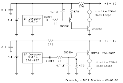
The pulse sequence represents the digital code of the particular key pressed along with possible manufacturer information. As the pulse train occurs, the 4.7uF capacitor is charged to about 3 volts and the capacitor voltage minus a diode drop appears across the 470 ohm resistor yielding a collector current from the 2N3904 or 2N3906 of about 5 milliamps. The collector current of the first stage flows into the base of the output transistor (MJE34 or 2N3053) which delivers around 250 mA into the indicator lamps. When the pulse train ends, the capacitor slowly discharges through the base of the first stage transistor allowing the Xmas tree lights to remain on for a about 1 second. The little Xmas lamps will operate over a wide voltage range, so you can use bulbs from almost any string, but bulbs from shorter strings (35 or less) will probably last longer operated at 5 volts.
The circuit can be powered from a small 9-12 volt DC, 250 mA or greater wall transformer. It may also need an additional 1000 uF filter capacitor across the DC output if the wall transformer does not have a built in capacitor. For use with a 9 volt battery, the incandescent lamps can be replaced with a regular LED and 680 ohm resistor and the output transistors can be replaced with small signal transistors (2N3904 or 2N3906). The total current drain will be about 25 mA with the LED lit, and 15 mA standby when the LED is off.
Monday, December 9, 2013
Pulse Timer Control Relay Circuit with IC555
Today we would like to offers solutions for a set time for take control relay and take NO. / NC. contact to apply to control other devices . such as disable or enable the device.function of this circuit is using IC555 to determine the pulse and a resistor R1 to the period of time.
Pulse Timer Control Relay Circuit Diagram

R1 #Seconds
100k 2
220k 3
470k 6
1M 15
The increase provides more time to increase the value of the Capacitor.
Part List
R1 = 1 Meg, Preset Pot
R2 = 10K
R3,R4 = 1K
C1 = 10uF, 16V
C2 = 0.01uF
T1 = BC547 (Gen Purp NPN)
T2 = 2N2222 (Hi Current NPN)
D1 = 1N4001 (Gen Purp Si)
IC1 = 555 (Lo-Power version)
RLA1 = Relay, 9V (amps of your choice)
Pulse Timer Control Relay Circuit Diagram
R1 #Seconds
100k 2
220k 3
470k 6
1M 15
The increase provides more time to increase the value of the Capacitor.
Part List
R1 = 1 Meg, Preset Pot
R2 = 10K
R3,R4 = 1K
C1 = 10uF, 16V
C2 = 0.01uF
T1 = BC547 (Gen Purp NPN)
T2 = 2N2222 (Hi Current NPN)
D1 = 1N4001 (Gen Purp Si)
IC1 = 555 (Lo-Power version)
RLA1 = Relay, 9V (amps of your choice)
Subscribe to:
Posts (Atom)