Showing posts with label sensor. Show all posts

Thursday, February 27, 2014

Cheapest Ever Motion Sensor

The RS-455-3671 sensor used in the Automatic Rear Bicycle Light project published in  the July/August 2010 edition can be replaced by a motion sensor that costs nothing instead of a fiver or thereabouts. 

Cheapest Ever Motion Sensor-image 
The replacement is a homemade device, built from components easily found in the workshop of any electronics enthusiast. Effectively it works as a variable resistor, depending on the acceleration force to which the device is  submitted. A prototype presented a resistance of 200 kΩ when not moving, and 190 kΩ when dropping about 1 cm.
Cheapest Ever Motion Sensor-Circuit diagram
Constructing is easy. Cut off a piece of about 10 mm of copper tubing. Take a piece of conductive foam, the kind used to protect integrated circuits. Cut a rectangular piece of 10  x 50 mm. Roll up firmly until it can be push-fitted securely into the copper cylinder. Then insert a conductive wire through the centre of the cylinder, bend it and (optionally) add protective plastic sleeving to each side. This is the first contact. Finally, solder a thin wire to the copper cylinder. This is the second contact. The foam resistance is pressure dependent. 

Consequently, when the device moves due to an external force, the inertia of the cylinder causes varying pressure in the foam, resulting in a small change of resistance between the inner conductor and  the cylinder. Because of that, it’s important to ensure the cylinder vibration is not restricted in any way by the connecting wire or the PCB. 

The comparator circuit shown here is capable of resolving the resistance change of the proposed foam/wire/copper sensor, allowing it to detect the motion of a vehicle for alarm or other purposes. 


Author : Antoni Gendrau – Copyright : Elektor
Read More..

Wednesday, February 5, 2014

Simple Acoustic Sensor

This acoustic sensor was originally developed for an industrial application (monitoring a siren), but will also find many domestic applications. Note that the sensor is designed with safety of operation as the top priority: this means that if it fails then in the worst-case scenario it will not itself generate a false indication that a sound is detected. Also, the sensor connections are protected against polarity reversal and short-circuits. The supply voltage of 24 V is suitable for industrial use, and the output of the sensor swings over the supply voltage range.
Circuit diagram :
simple Acoustic Sensor-Circuit Diagram
Simple Acoustic Sensor Circuit Diagram
The circuit consists of an electret micro-phone, an amplifier, attenuator, rectifier and a switching stage. MIC1 is supplied with a current of 1 mA by R9. T1 amplifies the signal, decoupled from the supply by C1, to about 1 Vpp. R7 sets the collector current of T1 to a maximum of 0.5 mA. The operating point is set by feedback resistor R8. The sensitivity of the circuit can be adjusted using potentiometer P1 so that it does not respond to ambient noise levels. Diodes D1 and D2 recitfy the signal and C4 provides smoothing. As soon as the voltage across C4 rises above 0.5 V, T2 turns on and the LED connected to the collector of the transistor lights. T3 inverts this signal.
If the microphone receives no sound, T3 turns on and the output will be at ground. If a signal is detected, T3 turns off and the output is pulled to +24 V by R4 and R5. In order to allow for an output current of 10 mA, T3’s collector resistor needs to be 2.4 kΩ. If 0.25 W resistors are to be used, then to be on the safe side this should be made up of two 4.7 kΩ resistors wired in parallel. Diode D4 protects the circuit from reverse polarity connection, and D3 protects the output from damage if it is inadvertently connected to the supply. 

Read More..

Saturday, February 1, 2014

Dual Level Liquid Sensor

This level liquid sensor electronic circuit diagram is based on a common Ca3410 operational amplifier IC . This level liquid sensor electronic circuit use two plates sensors ( two probes ) , one for the high level an one for low level .

Dual Level Liquid Sensor Circuit Diagram


If the level of the liquid is not in the adjusted range the LED will glow . The circuit require just a CA3410 operational amplifier and other few common components . This dual liquid level sensor require a 15 volt DC power supply circuit .
Read More..

Saturday, December 21, 2013

TSC230 Color Sensor

TSC230 - Color Sensor
Color Sensor TCS230 color sensor is a chip that works with the converting acceptance of a certain color of light emitted into the shape of frequency. TCS230 Color Sensor composed dri two main parts, namely a light-receiving section arranged in an array photodioda and Chaya koncerter this part to the frequency.


Basically the TCS230 Color Sensor is a light sensor which is equipped with light filters for RGB primary color (Red-Green-Blue) and light sensor without the filter with scale 8 bits for each of this part of the sensor.

Photodiode the TCS230 Color Sensor arrays arranged in 8 × 8 with the internal configuration of the photodiode. 16 photodiode for the light sensor with a red light filter. 16 photodiode for the light sensor with a green light filter. 16 photodiode for the light sensor with a blue light filter. And 16 photodiode for light sensor without a color filter. On the use of Color Sensor TCS230 we can choose the color sensor with a filter of what we want to set the configuration data S2 and S3.

Pin-Out TSC230
Pin-Out TSC230

Photodiode the TCS230 Color Sensor will issue a magnitude comparable with current levels of primary color of light that happened to him. This current is then converted into pulses with a frequency proportional to the amount of current. TCS230 Color Sensor Output frequency can be made by adjusting the scale of the configuration data S0 and S1 of the selector pins S0 and S1 Color Sensor TCS230.
Read More..

Thursday, December 12, 2013

Light sensor component

Electronic components are included in the category of light sensors are as follows:
- LDR
- Photo Transistor
- Photo Diode
- Infrared Receiver
The function of the electronic component is to detect the intensity of light received by the component. The light sensor is often used in electronic equipment such as on television, light a light switch, light intensity measuring instrument.
Read More..

Thursday, November 28, 2013

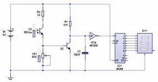
IR Infra Red Sensor with 7 Segment Display

Infrared light has a difference with ordinary light in general. We can see clearly when a light or light on an object.
As with the infrared light we can not see the manifestation of these rays. Frankly I can not answer when asked why the infrared rays are not visible in the eyes of us. So at night do not hope you can make light by using infrared light. One thing that is often heard from many people that infrared light can utilized for the functions of a camera that can see in dark conditions is often called an infrared camera.

Actually I have explained the working principles of electronic circuit section in this blog is about the basic working principle of a series of infrared sensors are simple. To design this sensor circuit you should not find trouble if you ever make another series of sensors. Its just that the sensor circuit consists of the transmitter and receiver, to learn the basic principles of this series of infrared you can see in the Basic Principles Series Infrared Transmitter and Receiver. In the circuit this time I try to utilize the output of this sensor circuit as a trigger circuit counter or counters.
IR (Infra Red) Sensor with 7-Segment Display

Picture series of infrared sensors | infrared sensor circuit scheme


Component List:

1. Resistors: R1 (33K), R2 (1K), VR1 (Potensio 100K)
2. Capacitors: C1 (100nF)
3. Transistors: Q2 (BC547 should)
4. Photo transistor: Q1
5. IC: 40 106 (Schimitt trigger), 4026 (Decade counter)
6. 7-Segment

WORKING PRINCIPLE:

In the transmitter circuit arrangement so that our task is only an infrared LED lights up and no shortage or excess of power, therefore, use 680 ohm resistors. On The set of photo transistor receiver serves as a useful tool sensor sensed a change in the intensity of infrared light. When infrared light is not on the photo transistor, the photo transistor is like a switch is open so that the transistor is in cutoff position (open). Because the collector and emitter open it in accordance with the laws of the voltage divider, the collector emitter voltage equal to supply voltage (logic high). The output of these collectors would make a series of counter counting irregularly if we did not dampen the bounce output to the input couinter. To reduce the bounce and clarify the logic signal to be our input to counter circuit, we use Schmitt trigger ignition. Schmitt trigger ignition is very useful for those of you who relate to digital circuits, eg, using the damping bounce of mechanical switches on the input digital circuit.

The series of counters that I use here is to use IC 4026 (Decade Counter), one of the family ic CMOS. IC counter counts up if this will get the clock input changes from logic low to high. This IC can directly connect it to the seven segment because the output is designed for seven segment mmang. So you do not need to use as a modifier decoder IC binary value into a score of 7-segment.
To menmgatur you can rotate the sensor sensitivity potensio VR1 at a critical point, or if necessary you can replace R2 with a more appropriate value.
Read More..