Showing posts with label 5a. Show all posts
Showing posts with label 5a. Show all posts
Saturday, October 11, 2014
Build a 1 2 36V 5A Adjustable Power Supply with LM317
Build a 1.2-36V 5A Adjustable Power Supply circuit diagram with LM317. This circuit is a simple power supply circuit. 1.2 - 36V adjustable bench power supply with 5A of output current. Max input voltage is 37V and output is adjustable via potentiometer between 1.2 up to 36 volts. TIP147 PNP darlington transistor boosts the current of LM317 from 100mA to 5A. LM317 is the most useful and inexpensive adjustable regulator and for this circuit you can also use LM317 L that can give 100mA, thats enough for transistor bias.
1.2-36V 5A Adjustable Power Supply Circuit Diagram
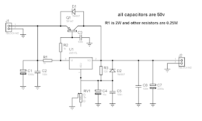
D1 and D2 are protection diodes because when you turn the circuit off the output capacitors are discharging and can damage the transistor or regulator. 100nf capacitors are in parallel with electrolytic capacitors to remove high frequency noise because large value electrolytic have large ESR and ESL and cant remove high frequency noise.

Sunday, December 8, 2013
Adjustable Power Supply 1 2 – 30V 5A using LM338
If you want to a variable dc voltage power supply circuit during 1.2V to 30Vdc and can provide a current maximum to 5A.
We may be have the many ways such as: to be modified the LM317 Variable Regulator 0-30V 1A by add the power transistor MJ2955 in circuit following Power supply regulator 1.2V-20V and 3V-6V-9V-12V 3Amp or will build the Variable dc regulator 0-30V 5A circuit to be well as well, But these methods. Rather cumbersome and wasting too money.

However we can build this circuit easily and cheap, By using the packages IC No. LM338 only one, Similar to the LM317 IC number, but it can supply up to 5A, as the circuit shown in Fig.
How this circuit works
-The transformer T1 converts the AC 220V to 24 Vac, so be rectified the current by the bridge diode rectifier BD1 – 10A 400V. Until DCV has come out that the filter capacitor C1 is equal to 35 volt.
-The IC1 is the heart of the operation of this circuit. By the voltage output value obtained from the IC depends on the voltage value at the Adj pin of IC1, or can be varied by adjusting the VR1.
-However output voltage will be approximately equal to 1.25+1.25VR1/R1
The output voltage at the output pin of the IC1 is a more powerful filter with the capacitor C3.
Subscribe to:
Posts (Atom)