Thursday, January 30, 2014

Most Power Supply for Amplifier


Power supply
As with most power amplifiers, the ±60 V power supply need not be regulated. Owing to the relatively high power output, the supply needs a fairly large mains transformer and corresponding smoothing capacitors—see circuit diagram below.

Most Power Supply for Amplifier
Note that the supply shown is for a mono amplifier; a stereo outfit needs two supplies. 

The power supply is straightforward, but can handle a large current. Voltage acserves as drive for the power-on delay circuit. The transformer is a 625 VA type, and the smoothing capacitors are 10 000 µF, 100 V electrolytic types. The bridge rectifier needs to be mounted on a suitable heat sink or be mounted directly on the bottom cover of the metal enclosure.. The transformer needs two secondary windings, providing 42.5 V each. The prototype used a toroidal transformer with 2x40 V secondaries. The secondary winding of this type of transformer is easily extended: in the prototype 4 turns were added and this gave secondaries of 2x42.5 V.
Read More..

Wednesday, January 29, 2014

Low power switching regulator

This circuit is a simple battery-powered switching regulator provides 5V out from a 9V source with 80% efficiency and 50-mA output capability. When Q1 is oon , its collector voltage rises , forcing current trhough the iinductor. The output voltage rises , causing A1s output to rise . Q1 cutts off and the output drops low enough for A1 to turn Q1. The 1 uF capacitor ensures low battery impedance at high frequencies , preventing sag during switching. See schematic diagram below :
Read More..

Tuesday, January 28, 2014

144 MHz Simple RF Detector Circuit

144 MHz Simple RF Detector Circuit
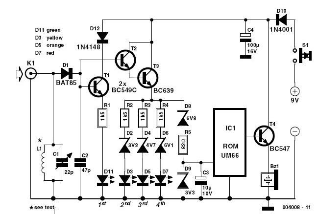
This simple circuit helps you sniff out RF radiation from your transmitter, improper joints, a broken wire or poor equipment with RF shielding. The tester is designed for the radio band amateur 2 meter (144-146 MHz in Europe). The instrument has a reading of 4-step LED and an audible alarm for high voltage radiation. The RF signal is received by an antenna and made to resonate by C1-L1. After rectification by the diode D1, the signal is fed to a two transistor Darlington amplifier HighGain, T2-T3. Assuming a 10-inch telescoping antenna using the RF level scale established for the LEDs is as follows:

When all the LEDs light, the (optional) UM66 sound / melody generator chip (IC1) also operates and provides an audible alarm. By changing the zener diode values ​​of D2, D4, D6 and D8, the step size and duration of the instrument may change as needed. To operate in other bands of ham or PMR, simply change the network-L1 C1 resonance.

For example, a transceiver 5 watt handheld equipped with a telescoping half-wave antenna (G = 3.5 dBd), there is an ERP (Effective Radiated Power) of just 10 watts and an emf of more than 8 volts near the head. Inductor L1 consists of 2.5 turns of 20 SWG (approximately 1 mm in diameter) enameled copper wire. The inner diameter is approximately 7 mm and no core is used.

Trimmer capacitor C1 associates is adjusted for the greatest number of LEDs to light at a relatively low fieldstrength position for a 2 m transceiver 145 MHz transmission. The tester is powered by a 9 V battery and consumes about 15 mA when all LEDs are on. Must be enclosed in a metal box.
Read More..

Monday, January 27, 2014

Universal PIC Programmer Circuit

Universal PIC Programmer Circuit
The series of Universal PIC Programmer can be used with software IC-Prog 1:05. Universal PIC programmer circuit is very simple with BC337 transistor 1 fruit, 2 pieces of IC regulators 7805 and 7808 as well as supporting passive components. Universal PIC Programmer series can be supplied with 2 pieces of 9V batteries.

For communication with computer circuit Universal PIC Programmer uses a serial RS232 port of computer. Then for the PIC to be programmed provided 5 lanes for the PIC that is DATA, Clock, Vpp, Vcc and Ground. For more details, can be directly seen in the figure below.

Universal PIC Programmer Circuit diaggram
Universal PIC programmer circuit diagram

The series of Universal PIC Programmer can be used to program the PIC family of 16F84A series, 12C509, 16C765 and the other. Hopefully this series of Universal PIC Programmer can help for friends who want to make PIC programmer.
Read More..

Sunday, January 26, 2014

Power amplifier circuit with IC LM386

IC LM386 is working for the amplifier audio circuit with a low power output , range from 0.325 watts to 2 watts with impedance 8 ohm. In this circuit requires voltage of 12 volts to the maximum work, and maximum current 3 Amp.
Components List :
R1=33K / 0,25W
R2=1K / 0,25W
R3=10R / 1W

C1=100n
C2=0,1uF/35V
C3=100uF/16V
C4=220uF/35V
C5=4,7uF/16V
IC1=LM386

Connector Instruction:
X-1  = Input , connect to output
X-2  = Input Ground
X1-1= V+ , 12 Volt DC
X1-2= V-/ Ground
X1-3= Speaker+
X1-4= Speaker-
Read More..

Saturday, January 25, 2014

Nicad Battery charger include voltage limiting

In this my circuit , which is one of a series of simple battery charger , but this circuit to charger the Nicad battery . This circuit included with current and voltage limting . Why use it ?? because with current voltage you can choose voltage to charge a battery , and the limiting voltage use limit voltage if the battery is fully, because if battery fully that damaged quickly.

See this schematic below :


Click to view Enlarge


Lamp 1 will glow brightly and the LED will be out when the battery is low or run out and the circuit is processing being to charged , but the LED will bright and the light dim when the battery is almost ready. Output voltage between 12 to 14 volt with current 100 mA.
Read More..

Friday, January 24, 2014

Digital Clock Based on Sam Gordon Theory

The circuit was designed to implement the concept of Sam Gordon in making a digital clock with visible components from the viewer of the clock.

  • Sam Clock – a digital clock equipment that is fully parametric or constantly varying with its parameters of function and construction, which has been operational for many years without problems on a 24 hour basis.
  • 74HC – a quad 2-input NAND gate with standard output capability, and is high speed Si-gate CMOS device that is pin compatible with low power Schottky TTL and specified in compliance with JEDEC standard no. 7A.
  • 74LS – a monolithic decade and binary counter that contains four master-slave flip flops and additional gating to provide a divide-by-two counter and a 3-stage binary counter with typical power dissipation of 45 mW and count frequency of 42 MHz.
  • 4060 – a 14-bit ripple counter with internal oscillator that has glitches which may occur in any logic gate systems connected to its outputs due to the slight delay before the later counter outputs respond to a clock pulse.
  • LM317 – an adjustable 3-terminal positive voltage regulator capable of supplying in excess of 1.5A over an output voltage range of 1.2V to 37V and requires only two external resistors to set the output voltage due to its internal current limiting, thermal shutdown and safe area compensation, making it essentially blow-out proof.
  • 4017 – a decade counter where the count advances as the clock input becomes high that may be combined with diodes for some functions such as flash sequences.
The main clock circuit consists of TTL and several CMOS represented by IC9 to IC13. The component combination drives the common cathode LED display while common anode can be driven when CMOS 4511 is replaced with 74LS47. Changing from common cathode to common anode would require the change of connection in DIS1 up to DIS5 display. A 1 Hz pulse frequency that comes from SL10 is divided in sequence by IC2 and IC4 within the region of the gates to make sure the indication of time in the format of Hours, Minutes, and Seconds. The tens of Hours are driven by Q1 with only the LED B and C of DIS6 display to indicate 1 to 12 for Hours indication. A small heatsink may be used to suppress the increase in temperature of Q1.

Digital Clock Based on Sam Gordon Theory

The supplied voltage of the circuit is shared into two lines where the 5 VA supplied with voltage in case of breakdown in network voltage, supplies all the ICs except the IC9 to IC13 which is being supplied by 5 VB. A battery is alternatively used in the case of interruption of circuit voltage. The second figure shows the indication of the display as it is driven by IC9 to IC13 where CMOS 4511 is used. The diodes DIS1 to DIS5 are conducting as common cathode while DIS6 will always be common anode. The use of 74LS47 will cause the DIS1 to DIS5 to conduct at common anode with their pins 1 and 6 going to the line of 5 VB with R39 and R40 to 0 V line. The dot in DIS3 and DIS5 is turned ON by these resistors to produce a division of LED displays.

There are two ways, found in the initial startup of operation, by which the 1 Hz pulse can be produced which constitute to the basis of time for the clock. The two methods consist of using a crystal oscillator with high oscillation frequency and the division of this frequency to create 1 Hz in the end. This would ensure a very précised and stable operation in producing the pulses. The crystal oscillator in figure 3 produces the 1 MHz frequency that is divided in stages from the IC15 up to IC17.

The gates A and B of IC18 and IC19 are not initially included in the operation unless the switches S1 or S2 are pressed to modify the time. Pressing the Super Fast (S1), would release a frequency pulse of 10 KHz while pressing Fast (S2) would release a pulse frequency of 100 Hz, to show indication to the display concerning the modification of time in a short interval. The figure 3 circuit is being supplied by 5 VA where the operation of oscillator is ensured, even in the event of voltage interruption, which would trigger the use of the battery.

Figure 4 also introduced the usage of crystal oscillator to produce 1 Hz in the output of SL19. This frequency is made possible by successive division 3.2768 MHz frequency coming from the oscillator, in the start of the operation. The presence of variable capacitor C3 is for altering the oscillator in order to test the frequency pulse at 204800 Hz. The indication of display is regulated by the switches S1 (fast) and S2 (super fast) for having a frequency of 10 Hz and 100 Hz respectively. The adjustment of time will be in a short interval, since the indication of display runs very fast. The use of mechanic switches is preferred due to simplicity. The circuit is similarly powered as in figure 3.

The fifth figure shows the power supply as it provides the necessary voltage for the operation of the circuit, together with the charging mechanism for the battery and the transfer in battery during voltage interruptions. The output from this supply circuit is regulated by the trimmer TR1 to produce 5 V at P1 to enable the functionality of the circuit. The next trimmer TR2 regulates IC25 as it gives 6.9 V at P2, which charges the lead acid battery which is rated 6V per 1 Ah, connected to SL17. During voltage interruption, the relay RL1 is triggered where its contacts connect the 5 VA line to the 6 V battery via the D5 and D6while 5 VB is connected to 0 V where the display stops.

Digital Clock Based on Sam Gordon Theory

The duration by which the contacts transfer from one state to the other is determined by C17. The IC24 and IC25 should be placed in a heatsink and be regulated with TR1 and TR2 without being connected to the supply circuit except during the use of batteries.The concept of the circuit is also embraced in other digital clocks. And because they are small inexpensive devices with LED displays, they are typically found in automobile clocks, desk clocks, microwave ovens, industrial clocks, computers, interval timers, radios, and televisions.
Read More..

Thursday, January 23, 2014

Motorcycle LED Lights Circuit

Motorcycle LED Lights series is so simple that it only uses a few components, but the results are very satisfactory. Power consumption is small enough 6 Volt course is suitable for your motorcycle.

The 555 circuit lower than is a flashing bicycle light powered with four C,D or else AA cells (6 volts). Two sets of 20 LEDs yearn for alternately glimmer by the side of approximately 4.7 cycles for every flash using RC morals publicized (4.7K pro R1, 150K for R2 and a 1uF capacitor). epoch intervals for the two lamps are in this area 107 milliseconds (T1, high LEDs) and 104 milliseconds (T2 junior LEDs). Two transistors are used to provide extra current away from the 200 mA limit of the 555 timer. A single LED is placed in vogue run with the center of the PNP transistor so with the aim of the inferior 20 LEDs ride inedible at what time the 555 output goes superior in the course of the T1 instance interval. The high output level of the 555 timer is 1.7 volts fewer than the supply voltage.

Motorcycle LED Lights

tallying the LED increases the accelerate voltage mandatory designed for the PNP transistor to a propos 2.7 volts so to the 1.7 volt difference from supply to the output is insufficient to turn on the transistor. both LED is supplied with about 20mA of current for a complete of 220mA. The circuit must labor with bonus LEDs up to about 40 used for both cluster, before 81 total. The circuit resolve too work with fewer LEDs so it possibly will come to pass assembled and tested with righteous 5 LEDs (two groups of two plus solitary) earlier than calculation the others.
Read More..

Wednesday, January 22, 2014

TBA820 low power audio amplifier

TBA820 , KA2201 , LM820 , U820 amplifier
At this time amplifier circuit based on IC KA2201, TBA820M, LM820M, and U820. You can use all ic is the series under the scheme. This amplifier circuit has a very small output power or low at 2W. Required supply voltage from 3 volts to a maximum of 16 volts.


Below is a scheme of this power amplifier

TBA820 , KA2201 , LM820 , U820 rangkaian amplifier
Part List
R1 = 100K
R2 = 120R
R3 = 100R
C1 = 100nF
C2 = 100uF
C3 = 470uF
C4 = 220pF
C5 = 47uF
C6 = 100uF
IC = KA2201 , LM820M , TBA820M , U820M
Read More..

Tuesday, January 21, 2014

15 V output regulated power supply circuit with uA723 and 2N3055

The supply receive from 220 /120/110 Volt AC , then lowered by the transformer . Then receives +20 Volts DC from rectifier / filter section. This applied to pin 11 and 12 of the IC uA723/LM723 , as well as to the collector of the 2N3055 series pass transistor. The output through R1 and R2, providing about 7 V with respect to ground at pin 4. The reference terminal at pin 6 is tied directly to pin 5 , the non inverting input of the error amplifier . For fine trimming the output voltage , a potentiometer can be installed between R1 and R2. A 100-pF capacitor from pin 13 to pin 4 furnishes gain compensation for the amplifier.
Base drive to the 2N3055 pass transistor is furnishes by pin of the uA723. Since desired output of the supply is 1 Ampere, maximum current limit is set to 1,5 Ampere by resistor Rsc whose value is 0,422 Ohm. A 100uF electrolytic capacitor is used for ripple voltage reduction at the output. A 1 kOhm output resistor provides stability for the power supply under no - load conditions. The 2N3055 pass transistor must be mounted on an adequate heatsink.
Read More..

Monday, January 20, 2014

Solid State Relays Circuit with TIL111

Solid state relays are almost everywhere these days, but they are very expensive. So, your efforts to build their own salary. Especially since it’s only a few parts and circuit simple and straightforward. Solid state relay is not really at all relays. There are no “relay” is available only with electronics, connection works. It works well as a relay, you can use low voltage higher and better. “Relay” between 115/220V AC wires in place, although it was customary, the neutral conductor and leave unchanged phases and neutral.

As long as no voltage (left in picture), the phototransistor TIL111 blocks of energy, and thus is not available. To ensure that the base TIL111 is fed to the transmitter (s) through the 1M resistor. This method prevents the base of transistor BC547B will be low and remains biased ‘on’. Collector is low and the gate (g) TIC106M thyristor, which is still in the country, “off”. 4-diode bridge rectifier circuit has no power apart from a small base and collector current BC547B, which is not enough to turn over the 330-ohm resistor TIC226M triac. Current “Load”, is very small.

Solid State Relays Circuit Diagram

With an input voltage, say 5 volts, the diode in the TIL111 lights up and activates the phototransistor. The voltage drop 1MEG ohm resistor in series with 22K resistance increases demand, which block the BC547B transistor. Collector current of the fact that the AC voltage falls below a certain value, which is VA. This ensures a sufficiently large voltage drop across the resistor 330 ohms triac switches ‘on’. The voltage on triac is currently only a few volts, so that practically the whole 115/220 AC voltage on the “Upload”.

The triac is a 100nF capacitor and impedance of 47 ohms, 100nF capacitor for the 330 ohm resistor is to protect the triac to be undesirable distortions caused by small peaks. To create the possibility of this circuit with different voltages to be switched, added BF256A FET. The FET acts as a current source from the source (s) with a gate (g). This means that this FET determines the current TIL111, regardless of the input voltage (up to a certain tolerance, of course). 1N4148 diode is to protect the circuit from reverse polarity.
(Tony: TIL111 is a so-called “optical coupling” with NPN output and can be replaced with NTE3042)

Good point line, as is the separation of AC and DC voltage, so this circuit is used in many applications, about 1.5 kW, when the triac is mounted on the large size of the cooling fins. “M” appears Triac means it’s 600volt type, “D” for 400V. So be sure to go to the M-type. NTE replacement for this circuit are 600volt types which are more than sufficient for our 110/115VAC. Even if you decide to print for this circuit is enough space between the lines AC and non AC these tracks to be close.
Read More..

Sunday, January 19, 2014

Light Activated Relay

This is same circuit as above with the addition of a photo resistor to trigger the flip flop instead of a push button. The bias resistor in series with photo resistor was chosen so that sufficient voltage is present at the base of the 2N3904 to supply current to the circuit in ambient lighting conditions. The circuit should toggle when the photo resistor is hit by a flashlight beam or other fast changing light source. Slow changes in light intensity will have no effect unless the light gets too bright to maintain sufficient bias for the 2N3904.

Light Activated Relay Circuit diagram :


Read More..

Saturday, January 18, 2014

9V FM Transmitter

This fm transmitter circuit is a very simple and require few external components and operates in FM band above 100 MHz.This fm transmitter needs to be powered from a 9 volts battery or from another 9 volts regulated power supply .The tuned coil L1, has two output tapping for the antenna connection, marked "A" and "B".

These are both low-level outputs and you choose which tapping you want to use ( stable low range, or more unstable but higher range). Tap B (2.5%) takes just a very small portion of signal from the oscillator circuit and therefore gives a very frequency stable transmitter. The output level (around 2.5mW) and range are therefore somewhat reduced.Tap A (10%) delivers very much more power (around 10mW) to the antenna load. This gives you a greater range, but at the expense of frequency stability. 

9V FM Transmitter Circuit diagram


All component leads should be kept as short as possible. The LINK wire on the PCB should lay flat on the PCB. Use the cutoff from a resistor leg.  Antenna length for circuit diagram transmitter varies with frequency for optimum distance: 90MHz 80 cm, 95MHz 75cm, 100MHz 70 cm, 105 MHz 68 cm.The frequency determining elements (L1, C5 and C6) form a simple LC tuned oscillator. The inherent problem with this type of circuit diagram transmitter is that any external load (antenna) will change the operating frequency.
Read More..

Friday, January 17, 2014

2800W high power audio amplifier

Mono high power amplifier is actually a powerful 1400 W, but if this hihgh power amplifier circuit is doubled and you want to create stereo, high power amplifier the necessary components and pcb requires two-fold. So if the stereo high power amplifier 2 X 1400W. Schematic Circuit diagram is still less by looking at the circuit that was so below, the finished circuit has been added with a gains using JRC4558 IC by the two and the picture ic where it can be seen below. For circuit buffers, drivers, and booster use multiple transistors and other components (can be seen listed component). And high power amplifier project that is so below is just part of the buffer and driver while the booster has not been made​​. For additional transistors in the booster or high power amplifier end scheme can be found Booster output power amplifier.
2800W power amplifier
Click schematic to view larger
Part List :

Resistor
R1_____560Ω
R2_____100Ω
R3_____2K2Ω
R4_____560Ω
R5_____1Ω
R6_____27KΩ
R7_____10KΩ
R8_____100Ω
R9_____100Ω
R10____100Ω
R11____12KΩ
R12____100Ω
R13____100Ω
R14____100Ω
R15____27KΩ
R16____2K2Ω
R17____560Ω
R18____100Ω
R19____10KΩ
R20____330Ω
R21____47Ω 2W
R22____56Ω
R23____2K2Ω
R24____22Ω
R25____56Ω
R26____180Ω
R27____500-1KΩ Trim
R28____560Ω
R29____56Ω
R30____56Ω
R31____22Ω 1W
R32____5Ω6 2W
R33____10Ω
R34____180Ω
R35____100Ω
R36____22Ω 2W
R37____180Ω
R38____56Ω
R39____47Ω 2W
R40____5Ω6 2W
R41____10Ω
R42____10Ω
R43____10Ω
R45____10Ω
R46____0.22Ω 5W
R47____0.22Ω 5W
R48____0.22Ω 5W
R49____0.22Ω 5W
R50____10Ω 5W

Capacitor
C1_____1цF
C2_____1.5nF
C3_____0.1цF 250-275V
C4_____0.1цF 250-275VC5_____100nF
C6_____100цF 50V
C7_____39pF
C8_____330pF
C9_____330pF
C10____330pF
C11____47nF 250-275V
C12____220nF 250-275V

Transistor
T1_____MJE340
T2_____2N5551 / C2240
T3_____2N5551 / C2240
T4_____2N5551 / C2240
T5_____2N5551 / C2240
T6_____2N5401 / BF423
T7_____2N5401 / BF423
T8_____2N5401 / BF423
T9_____2N5401 / BF423
T10____MJE350
T11____B1186
T12____TIP127
T13____D1763
T14____D1763
T15____B1186
T16____C5198
T17____A1941
T18____2SC2922 / MJ15024G
T19____2SC2922 / MJ15024G
T20____2SA1216 / MJ15025G
T21____2SA1216 / MJ15025G
2800W power amplifier circuit
This installation include gain JRC4558

2 x 1400W high power amplifier
This is pcb design

high power amplifier 1400W
Installation with booster
PCB design by SIGMA-4 Madiun ©

Other high power amplifier circuit : 1500W HiFi Power Amplfier
Read More..

Thursday, January 16, 2014

Mini Portable Guitar Amplifier

This
small amplifier was intended to be used in conjunction with an
electric guitar to do some low power monitoring, mainly for practice,
either via an incorporated small loudspeaker or headphones. The
complete circuit, loudspeaker, batteries, input and output jacks can be
encased in a small box having the dimensions of a packet of
cigarettes, or it could be fitted also into a real packet of cigarettes
like some ready-made units available on the market.
This design can be used in three different ways:
  1. Loudspeaker
    amplifier: when powered by a 9V alkaline battery it can deliver about
    1.5W peak output power to the incorporated loudspeaker.
  2. Headphone
    amplifier or low power loudspeaker amplifier: when powered by a 3V
    battery (2x1.5V cells) it can drive any headphone set type at a
    satisfactory output power level or deliver to the incorporated
    loudspeaker about 60mW of output power. This configuration is useful for
    saving battery costs.
  3. Fuzz-box: when powered by a 3V battery
    (2x1.5V cells) and having its output connected to a guitar amplifier
    input the circuit will behave as a good Fuzz-box, showing an output
    square wave with marked rounded corners, typical of valve-circuits
    output when driven into saturation.

mini portable guitar amplifier circuit schematic
Parts:

R1______________22K 1/4W Resistor
C1______________10µF 25V Electrolytic Capacitor
C2_____________100nF 63V Polyester or Ceramic Capacitor
C3_____________220µF 25V Electrolytic Capacitor
IC1__________TDA7052 Audio power amplifier IC
J1,J2__________6.3mm Stereo Jack sockets (switched)
SPKR___________8 Ohm Loudspeaker (See Notes)
B1________________9V PP3 Battery or 3V Battery (2 x 1.5V AA, AAA Cells in series etc.)
Clip for PP3 Battery or socket for 2 x 1.5V AA or AAA Cells

Notes:
  • For
    the sake of simplicity and compactness, this unit employs a dual
    bridge IC amplifier and a few other parts. For the same reason no
    volume or tone controls are provided as it is supposed that the
    controls already existing on the electric guitar will serve
    satisfactorily to the purpose.
  • No power switch is used: the
    battery voltage will be applied to the circuit when the input plug will
    be inserted in the input jack socket J1. For this purpose be sure that
    the input plug is a common 1/4 inch guitar mono jack plug and J1 is a
    1/4 inch stereo jack socket.
  • The output jack socket J2 must be a
    switched stereo type. The changeover switching is arranged in such a
    way that, when a common headphones stereo jack plug is inserted into
    the socket, the loudspeaker will be disabled and the mono output signal
    will drive both the headsets in series, allowing full headphone
    reproduction. When used as a Fuzz-box output, a mono jack plug must be
    inserted into J2.
  • If the amplifier is intended to be encased in a packet of cigarettes, standard loudspeaker diameter should be 57 or 50mm.
Technical data:

Max output power: 1.5W @ 9V supply - 8 Ohm load; 60mW @ 3V supply - 8 Ohm load
Frequency response: Flat from 20Hz to 20kHz
Total harmonic distortion @ 100mW output: 0.2%
Max input voltage @ 3V supply: 8mV RMS
Minimum input voltage for Fuzz-box operation: 18mV RMS @ 3V supply
Current consumption @ 400mW and 9V supply: 200mA
Current consumption @ 250mW and 9V supply: 150mA
Current consumption @ 60mW and 3V supply: 80mA
Quiescent current consumption: 6mA @ 9V, 4mA @ 3V supply
Fuzz-box current consumption: 3mA @ 3V supply
Read More..

Wednesday, January 15, 2014

Analog Versatile Circuit MIC 640 Acquisition System

This tour, available in Stainless DIL 8 legs, can measure 4 analog voltage independent between 0 and 5 volts, and send the result of this measure in the form of four characters on a standard asynchronous serial link. Its serial output is directly TTL or CMOS compatible and can be connected to a serial input RS 232 by simply adding a resistor.

The MIC 640 can operate in automatic mode, thus sending the result of four steps every second, or in command mode, in which case it sends the result of four measures under the control of external logic signal. In this latter method that we use here.

Its consumption is extremely low, it is possible to feed signals from the unused serial port RS 232, subject of course not to waste the little energy available in external circuits involved too greedy.

This circuit, easily available in France, costs less than 18 euro which makes it an ideal candidate for this achievement we will find the schema without tarder.Si you want more information about the MIC 640;s complete data sheet entirely in French, is available for download by clicking this link.

Schematic acquisition module

Analog Versatile Circuit  MIC 640 Acquisition SystemAnalog Versatile Circuit MIC 640 Acquisition System

The heart of the module is obviously the MIC 640, spotted IC1 on the figure below. It is directly connected to the serial input RS 232 PC via limiting resistor R1 current.

His entry called CTRL to define its mode of operation. Left to the body, it makes it automatically perform a conversion on each input per second, whereas if it is reduced to levels as high as in this case, it triggers a conversion of each entry at each grounding.

These earthed take place through the transistor Q1 controlled by the serial data output TXD of RS 232, via the diode D4. This same output is through the diode D3 and this time the capacitor C3, to produce the negative supply voltage of the input stage that we discover in a moment.

The control lines DTR and RTS serial interface they provide for the positive supply via diodes D1 and D2. This voltage is unregulated, is the positive power of the input stage. By cons, it is regulated to 5 volts through IC2 so that it feeds a voltage very stable MIC 640.

As the current and available for both the positive supply for the negative supply is still low (10 mA max), I had to carefully choose the components used and they will not be replaced under any pretext. IC2 is indeed a regulator 5 volts 3 feet very low: in one case in 2936 SM Z5 which absorbs only 500 uA. For information, its "equivalent" the 78L05 consumes 3 mA in the same situation!

The input stage meanwhile was achieved using four operational amplifiers effect transistor field-mounted voltage followers. This confers to the module input impedance greater than 100 MW. All four amplifiers are combined in one box, referenced LF 444 at National Semiconductor, whose total consumption does not exceed 800 uA for the four amplifiers! Again, no question of putting such a TL 084 which face voracious with its 5.6 mA!

This input stage is protected from excessive voltages through resistors R7 to R10 and diodes D6 to D13. If you precede the various stages of converting physical quantities / voltage, you can possibly do without protection diodes that degrade somewhat the very high input impedance of 444 MQ due to their leakage current. It is in fact only 50 pA maximum input of 444 LF while a diode, even small leaks, easily misses 1 nA or 20 times more!
Read More..

Tuesday, January 14, 2014

Power Supply with regulation

power supply universalElectronic devices should be powered by direct current supply of DC (direct current) which is stable in order to work properly. The battery or batteries are the source DC power supply is best. However, for applications that require power supplies larger, the source of the battery is not enough.
A major source of power supply is alternating source of AC (alternating current) from power plants. For that needed a power supply device that can convert AC current into DC. In this article presented the principles of the power supply circuit (power supply), linear start from the simplest rectifier circuit to the power supply was regulation.

Power supply is functioning electronic circuit to supply power to other components in perangakat electronics. All electronic components that exist in an electronic device will receive power supply from the power supply. Power supply is very has a very important role in an electronic device. Therefore, without power supply, an electronic device will not work. The common voltage supplied by the power supply is +5 V, +12 V,-5V,-12V.
Large output voltage of power supply also must we adjust the voltage needs burden or our electronic devices. Because, an electronic device will be able to work well if the supply voltage and power to him just like the specifications of these electronic components. (specification can be seen in the datasheet of a component).
simple power supply schematic

Power supply circuit drawing examples above we can replace with our needs. Pictured above is a simple power supply circuit having 78XX LM as a regulator. Type LM 78XX can we replace it according to our needs. If for example we want the output from the power supply is +12 Volts, then we have to change it into LM7812 LM. And also of course we have to input voltage of +12 volt transformer.

Similarly, if we want a voltage of +5 volts. So we have to replace the LM7805 LM 78XX, and the input voltage from the transformer 5Volt (transformer).
Read More..

Monday, January 13, 2014

24V DC Powered Beeper with 4 Separate Inputs

24 Volt DC is a very prevalent voltage used fashionable developed settings. This hobby circuit lower was designed to acknowledge four unlike 24v DC alarm input signals, which are followed by used to drive a single low power beeper. The beeper is a magnetic type with its own oscillator/driver. The four diodes form an “or else” gate so one solitary of the four inputs want cause the beeper to produce blast. A CMOS version of the widely held 555 timer is used to strobe the beeper on and rancid on something like 1Hz.

24V DC Powered Beeper with 4 Separate Inputs Circuit Schematic Diagram

Copyright: Discover Circuits
Read More..

Sunday, January 12, 2014

Photo Transistor Detector


All of the circuits on the PCB are configured so with the intention of as the photosensors are dark, the output of the 556 timers want stay peak. The issue delay period of each one 556 timer can be tainted by selecting as it should be combination ideals representing the R7/C2, R8/C3, R9/C4 and R10/C5 pairs.The LM339 input detection voltage levels for the circuit while publicized is settle on on 1/2 of the supply voltage. If a subordinate before elevated detection level voltage is wanted, the standards of resistors R5 and R6 can be there misused to suit.hint as soon as power is functional to the circuit, the outputs of the 556 timers pray be piercing in place of 1 discharge delay period phase. (Until the timing capacitors hold charged to 2/3rds of the supply voltage.) in attendance are RESET inputs for apiece LM556. 

Photo Transistor Detector
These inputs complete not have terminal stop contacts but do have pads with holes to solder wires to if considered necessary. The RESET inputs might take place used to force the outputs of the 556 timers LOW until the timing capacitors have fully charged behind power is practical to the circuit but an outer timer would be required to accomplish this.This circuit does not require a regulated power supply and can carry on on supply voltages of up to 15 volts.

on behalf of in turn on other light detector circuits, comprehend Light Activated Detector Circuits by the side of this put.For added broad in a row on Voltage Comparators see the Voltage Comparator in sequence piece of paper by the side of this place.on behalf of further universal in sequence on LM556 timers see the 555 Timer Information bleep next to this place.threatening - If the polarity of the power supply for this circuit is reversed before the circuit is connected to an AC or else DCC source this circuit pray exist damaged. The most supply voltage meant for this circuit is 15 Volts.
Read More..

Saturday, January 11, 2014

Auto Sound Systems Should be Superior Quality

I for one cant imagine entering into my daily commute without the sound assistance of a good auto sound system. Music in the morning is as necessary for me as oxygen and caffeine. If I live without any of those above my day is already up and running with wrong foot first. Music is a very important part of any given day for someone like me.

Auto SoundsMy wake up call in the morning comes in the form of my favorite radio station and from that point on I have music as my companion for the vast majority of my morning routine. That is of course with the exception of children and husband and some of their more insistent demands for food, money, and last minute homework crisis. I will gladly take my music and tea most mornings and skip the drama.

The point of all this is that I am not alone in my morning preference. If I were there wouldnt be so many variations of the music driven alarm clock. Today you can even have CD player alarm clocks in order to get you up and running to your favorite tunes. Of course this brings me to an important point. A good auto sound system will sound much better than your morning music wake up call. Most alarm clocks will not have the best quality of sound. They are designed for minimal space, minimal intrusion, and to be annoying enough that you will get up (eventually) and turn them off. If the music is good and the quality even better, most of us, can manage to incorporate the music into our dreams and go right back to sleep.


While you do not want your auto sound system to necessarily put you to sleep you do want it to be enjoyable to listen to. You are after all most likely shelling out a good portion of a months salary in order to pay for it. Some may say this is extravagant but many people spend more time each week in their cars than they do in front of their televisions and are much more inclined to spend a great deal more on big screen or LCD televisions for their homes. I like being surrounded by nice things and music is one of those things. A great auto sound system is one way that I can bring music into my life day in and day out. I am quite certain that there are others out there just like me. Just like the alarm clock radios, there are many wonderful auto sound systems on the market today competing with one another for a slice of the music lovers pie. That would not be the case if there were only a select few of us who enjoyed great music.


The trick is always going to be finding the sound you like at a price that is just as delightful as the sound they provide. A good auto sound system is not an impulse buy. This is something you consider carefully, shop around, and compare prices on before you make the decision to purchase. Also consider things such as free installation and how they will affect the overall price when the time comes. It could very well be that the same sound system will cost a different amount at several different stores, if one of those stores offers free installation (depending on the cost of installation) it may be a much better deal even if the cost of the system is slightly greater than those at the other competing stores.

There are many things to consider when purchasing an auto sound system for your vehicle. The most important of those things is how well you like the system you are purchasing. This is your money after all and you should spend on the systems that sounds best and offers the most features that you desire.

Read More..

Friday, January 10, 2014

1000Watt Audio Power Amplifier Blazer Circuit

1000Watt Audio Power Amplifier Blazer Circuit1000Watt Audio Power Amplifier Blazer Circuit


This is a audio power amplifier Blazer circuit provides up to 1000Watt . This fascinating routes several sensible bass and treble alive. Importantly ought to opt for Power offer supply, that has been fairly high voltage category 70Vdc GND -70V 10A is that the current low level.


The transistors are 2SC3858 (NPN) and 2SA1494 (PNP), and have high bandwidth, wonderful safe operating space, high linearity and high gain. Driver transistors are 2SC5200 (NPN) and 2SA1943 (PNP). All devices are rated at 230V, with the facility transistors having a 150W dissipation and also the drivers are 50W.


This circuit describes an amplifier, power offer and tests procedures that are all inherently dangerous. Nothing described during this article ought to even be thought-about unless youre totally experienced, grasp specifically what youre doing, and are willing to require full 100% responsibility for what you are doing. There are aspects of the look which will need analysis, fault-finding and/or modification.

Read More..

Thursday, January 9, 2014

Low Power Audio Amplifier Circuit with IC TDA2824S

This is stereo audio amplifier with based on ICTDA2824S , Minimum voltage require 3 volts and maximum voltage 17 volts . Maximum output power 2 X 2 Watt , its low power amplifier. Output impedance  4 ohm. see schematic audio below :
Read More..

Simple 6V charger battery circuit

This is very simple charger 9V - 30V battery charger with main operation by IC LM317L and 2N222 transistor. Direct input DC voltage , the recomended capacitor is 1000uf. It can be filtering Output voltage and make long-lasting battery. And easy to make this circuit , without using the PCB would be able to.
See the Charger Schematic and troubleshooting below :
If it cant working , then the mistakes and keeping the following :
  • Check input voltage, whether working or not.
  • Check the installation of the pins of components.
  • Chek transistor , at input voltage , base , and output voltage.
  • Check IC input voltage and output voltage , there or not.

Thank  you 4 visiting my blog.
Read More..