Sunday, February 9, 2014

AVR Dongle Circuit

This circuit is intended to program AVR controllers such as the AT90S1200 via the parallel port. The circuit is extremely simple. IC1 provides buffering for the signals that travel from the parallel port to the microcontroller and vice versa. This is essentially everything that can be said about the circuit. The two boxheaders (K2 and K3) have the ‘standard’ ISP (in system programming) pinout for the AVR controllers. The manufacturer recommends these two pinouts in an attempt to create a kind of standard for the in-circuit programming of AVR-controllers. These connections can be found on many development boards for these controllers. The software carries out the actual programming task.

Circuit diagram :
AVR_Dongle_Circuit_Diagramw
AVR Dongle Circuit Diagram

It is therefore necessary to have a program (ATMEL AVR ISP), which is available as a free download from http://www.atmel.com. The construction of the circuit will have to made on standard prototype board, since we didn’t design a PCB for this circuit. This should not present any difficulties considering the small number of parts involved. We recommend that inexperienced builders first make a copy of the circuit and cross off each connection on the schematic once it has been made on the board. This makes it easy to check afterwards whether all connections have been made or not.

http://www.ecircuitslab.com
Read More..

10 Watt Power Amplifier Circuit

IC BA514 its the main of  this circuit. This is actually low power output with minimum power output 2 W but maximum output 10W . Minimum voltage require 9 Volt and maximum voltage 14 Volt . Impedance output 4 Ohm.
Power Amplifier Schematic below :


Click to view Larger
All capacitor with uF and minimum voltage capacitor is 16 V. resistor with 1/4 Watt.
Read More..

Power Supply with principle of UPS

power supply voltage
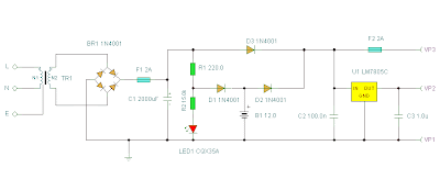
For UPS Power Supply circuit consists of lowering the voltage, rectifier, charger, batery and regulators. The technique is applied from UPS on the power supply is the use of batery and charger is connected dengang direct coupling with a series diode. For more details can be seen with the following image.

Ups power supply schematics
Schematics
The rectifier in the circuit UPS Power Supply For this to function also as a charger via D1. D3 function is to drain-source voltage of the rectifier to the regulator circuit, when the AC voltage source. D2 serves to drain the batery when the source voltage from AC voltage source does not exist. batery configuration and diode D1, D2 and D3 is adopted from the UPS system. may be useful and can provide inspiration on teman2 all in making backups on the system power supply voltage.
Read More..

Saturday, February 8, 2014

4 Transistor Transmitter Schematic

This circuit provides an FM modulated signal with an output power of around 500mW. The input Mic preamp is built around a couple of 2N3904 transistors, audio gain limited by the 5k preset. The oscillator is a colpitts stage, frequency of oscillation governed by the tank circuit made from two 5pF capacitors and the inductor. ( Click here for Colpitt Oscillator Resonant Frequency Equation.) Frequency is around 100Mhz with values shown.

4 Transistor Transmitter Circuit Diagram


Audio modulation is fed into the tank circuit via the 5p capacitor, the 10k resistor and 1N4002 controlling the amount of modulation. The oscillator output is fed into the 3.9uH inductor which will have a high impedance at RF frequencies.

The output stage operates as a class D amplifier, no direct bias is applied but the RF signal developed across the 3.9uH inductor is sufficient to drive this stage. The emitter resistor and 1k base resistor prevent instability and thermal runaway in this stage.
Read More..

Schematic Power Amplifier with IC TDA7370

Here..... this circuit is stereo power amplifier , based on IC TDA7370, its nice Intregated Power amplifier , He does not have hre slightest sound buzzing , although power amplifiers without additional reinforcement , such as filters , tone control, etc.
Voltage                      : 9 to 24 volts
Max. Power Output  : 2 x 20 Watts
Impedance                : 4 Ohms
Read More..

12V Speed Controller Dimmer

This handy circuit can be used as a speed controller for a 12V motor rated up to 5A (continuous) or as a dimmer for a 12V halogen or standard incandescent lamp rated up to 50W. It varies the power to the load (motor or lamp) using pulse width modulation (PWM) at a pulse frequency of around 220Hz.  SILICON CHIP has produced a number of DC speed controllers over the years, the most recent being our high-power 24V 40A design featured in the March & April 2008 issues. Another very popular design is our 12V/24V 20A design featured in the June 1997 issue and we have also featured a number of reversible 12V designs.
 
Project Image :
12v-speed-controllerdimmer pro
 12V Speed Controller/Dimmer Project Image

For many applications though, most of these designs are over-kill and a much simpler circuit will suffice. Which is why we are presenting this basic design which uses a 7555 timer IC, a Mosfet and not much else. Being a simple design, it does not monitor motor back-EMF to provide improved speed regulation and nor does it have any fancy overload protection apart from a fuse. However, it is a very efficient circuit and the kit cost is quite low.

Parts layout:

12v-speed-controllerdimmer2_Parts layout

Connection diagram:

12v-speed-controllerdimmer3_Connection diagram

There are many applications for this circuit which will all be based on 12V motors, fans or lamps. You can use it in cars, boats, and recreational vehicles, in model boats and model railways and so on. Want to control a 12V fan in a car, caravan or computer? This circuit will do it for you. The circuit uses a 7555 timer (IC1) to generate variable width pulses at about 210Hz. This drives Mosfet Q3 (via transistors Q1 & Q2) to control the speed of a motor or to dim an incandescent lamp.

Circuit diagram :
12v-speed-controllerdimmer Circuit diagram
12V Speed Controller/Dimmer Circuit Diagram

While the circuit can dim 12V halogen lamps, we should point out that dimming halogen lamps is very wasteful. In situations where you need dimmable 12V lamps, you will be much better off substituting 12V LED lamps which are now readily available in standard bayonet, miniature Edison screw (MES) and MR16 halogen bases. Not only are these LED replacement lamps much more efficient than halogen lamps, they do not get anywhere near as hot and will also last a great deal longer.

Source : Silicon Chip
Read More..

5 1 surround amplifier circuit schematic

This 5.1 surround amplifier circuit schematic use the IC AN7168 as the main component from this circuit . Minimum voltage required 12V and maximum voltage 24V , I recomended it 12 V because the voltage support on are components. But if you want to better a loud sound you can raise it. 

Maximum power output 40W with impedance 4 ohm . This 5.1 surround amplifier circuit schematic also support to make surround sound or 5.1 speaker. Use this amplifier on rear speaker , left right , and center but dont use to subwoofer speaker. See 5.1 surround amplifier circuit schematic below :

Click to view large
If you want to make a 5.1 surround sound you must make 5 the circuit of 5.1 surround amplifier circuit schematic , for left and right speaker , rear left and right speaker , and center speaker. Use the subwoofer speaker with support amlplifier subwoofer circuit .


Read More..