Tuesday, February 4, 2014

Regulator power supply with op amp

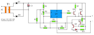
Power supply circuit has a first amplifier using op-amp is IC uA741. Op amp circuit that is used only one, but it also features an adjustable voltage, which is steered by a trimpot resistors. Rtrim will set the input to the IC input on pin 2, so that if the detainee on Rtrim which will be channeled into ic enlarges the output voltage will be small, and otherwise. After the voltage is boosted and filtered and then the voltage will be regulated and boosted again by a NPN transistor.
op-amp regulator power supply
Output voltage 0.5V - 35V
Part List :
Resistor
R1____1K5
R2____1K trim
R3____10K
R4____330R
R5____1K
R6____47R
R7____68R
R8____820R
R9____47K
R10___22K
R11___1K5

Capacitor
C1____10000uF 80V

Transistor
Q1____2N3565
Q2____2N3565
Q3____S9013
Q4____S9013

Diode
D1____1N4007
D2____1N4007
LED1_Red Led

IC
U1____uA741 (op-amp ic)
Read More..

18W Amplifier Schematic Circuit

18W Amplifier Schematic Circuit

18W Amplifier Schematic Circuit Part List

P1_____________22K Log. Potentiometer (Dual-gang for stereo)

R1______________1K 1/4W Resistor

R2______________4K7 1/4W Resistor

R3____________100R 1/4W Resistor

R4______________4K7 1/4W Resistor

R5_____________82K 1/4W Resistor

R6_____________10R 1/2W Resistor

R7_______________R22 4W Resistor (wirewound)

R8______________1K 1/2W Trimmer Cermet (optional)

C1____________470nF 63V Polyester Capacitor

C2,C5_________100µF 3V Tantalum bead Capacitors

C3,C4_________470µF 25V Electrolytic Capacitors

C6____________100nF 63V Polyester Capacitor

D1___________1N4148 75V 150mA Diode

IC1________TLE2141C Low noise, high voltage, high slew-rate Op-amp

Q1____________BC182 50V 100mA NPN Transistor

Q2____________BC212 50V 100mA PNP Transistor

Q3___________TIP42A 60V 6A PNP Transistor

Q4___________TIP41A 60V 6A NPN Transistor

J1______________RCA audio input socket

Power supply parts:

R9______________2K2 1/4W Resistor

C7,C8________4700µF 25V Electrolytic Capacitors

D2_____________100V 4A Diode bridge

D3_____________5mm. Red LED

T1_____________220V Primary, 15 + 15V Secondary, 50VA Mains transformer

PL1____________Male Mains plug

SW1____________SPST Mains switch
Read More..

Car Battery Voltmeter with LED Indicator

The circuit was developed to create a voltmeter that will be used to test car batteries while showing an indication using LEDs.

  • Voltmeter – a device or an instrument used for measuring the electrical potential difference between two points of either alternating current or direct current electric circuit.
  • LM324 – has internal frequency compensated for unity gain, large DC voltage gain, wide bandwidth, wide power supply range, very low supply current drain, low input biasing current, low input offset voltage, large output voltage swing and differential input voltage range equal to the power supply voltage.
The voltage of a car battery can be measured with the use of a voltmeter as well as the charge left. A typical car battery voltage delivers around 12.6 V under no load condition and will require charging if the voltage reading is at 11.6 V. The measurement of voltage is best recommended during a high current like running the car head lights into high beam. In case the battery rapidly drops its voltage significantly under load, it would require a replacement.

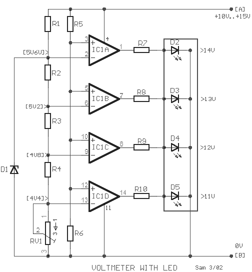
This circuit will function as a comparator and will measure the car battery voltage with an interval or step of 1 V. The voltmeter will be connected across the battery terminals then starting the car. The voltage of the battery should not be measured below 10 V or else it will be considered as low in charge or low in water, since the water level of the battery should be about ¼ of an inch above the plates.

Car Battery Voltmeter with LED Indicator Schematic


Car Battery Voltmeter with LED Indicator

By applying the voltage of the battery in the inverting inputs of the amplifiers, the indicated voltage on the voltmeter is compared with the reference voltages that are produced by the Zener diode D1. The Zener diode is a special kind of diode that permits the flow of current in just one or forward direction as a normal diode, but will also allow in the reverse direction if the voltage is above or larger than a certain value of the breakdown voltage. The measured value is just enough to provide good thermic stability.

The presence of 10K trimmer RV1 is to adjust the degree of voltage that is required or desired while the visual indication will originate from the four LEDs.

R1=1K2
R2-3-4=680R
R5=15K

R6=10K
R7-8-9-10=1K
D1=5V6 /0.5W Zener

D2-3-4-5=LED
IC1=LM324
RV1=10K trimmer

The main use of the car battery voltmeter is to monitor the life and performance of batteries. It can be mounted on the dashboard that shows the battery condition to easily monitor the electrical system voltage while driving. The measurement is done by switching off the engine as well all lights and accessories and switching on the key without starting the engine. The battery is full charge if the voltmeter reads 12 V or more while a voltmeter reading of much less than 12 V signifies the battery is either discharged or failing.
Read More..

Diagram Basic RF Oscillator


This basic circuit is simple to create and the tools are not critical . Most of them can be found in your junk parts box .
The L1 antenna coil can be made by close winding 8 to 10 turns of 22 gauge insulated hookup wire around a
1/4 inch form such as a pencil .
You can exeprement with the size of the copile and the number of  turns to see how it affects the frequency and singnal out put of the oscilatter .
You ought be able to pick up its signal with a standard FM radio receiver . The signal in ought be coupled by a disc capacitor of about 0.1 uF to stage in main of it .

Author 
          Saifullah soomro
Read More..

Monday, February 3, 2014

Mains Slave Switcher II

As a guide, a one-inch reed switch with 40 turns reliably switched on with the current flowing through a 150-watt lamp (approx. 625 mA) but larger reeds may require more turns. If the master appliance draws less current (which is unlikely with power tools) more turns will be required. The reed switch is used to switch on transistor T1 which in turn switches the relay RE1 and powers the slave appliance. Since reed switches have a low mechanical inertia, they have little difficulty in following the fluctuations of the magnetic field due to the alternating current in the coil and this means that they will switch on and off at 100 Hz.

Circuit diagram:
mains-slave-switcher-circuit diagram
Mains Slave Switcher II Circuit Diagram

C3 is therefore fitted to slow down the transistor response and keep the relay energised during the mains zero crossings when the current drawn by the appliance falls to zero and the reed switch opens. C1 drops the mains voltage to about 15 V (determined by zener diode D1) and this is rectified and smoothed by D2 and C2 to provide a d.c. supply for the circuit. The relay contacts should be rated to switch the intended appliance (vacuum cleaner) and the coil should have a minimum coil resistance of 400 R as the simple d.c. supply can only provide a limited current. C1 drops virtually the full mains voltage and should therefore be a n X2-class component with a voltage rating of at least 250V a.c.

Warning:
The circuit is by its nature connected directly to the mains supply. Great care should therefore be taken in its construction and the circuit should be enclosed in a plastic or earthed metal box with mains sockets fitted for the master and slave appliances.


http://www.ecircuitslab.com
Read More..

Sunday, February 2, 2014

PWMMotor Driver

As the title "PWM DC Motor Driver with Forward / Reverse and Breaking" this series is a PWM DC motor controller that can control DC motors with clockwise rotation and counter-clockwise and is equipped with a braking system. 


In a series DC motor control PWM DC Motor Driver with Forward / Reverse and Breaking use this system for SASL PWM DC motor rotation speed. Power driver in a series DC motor PWM DC Motor Driver with Forward / Reverse and Breaking uses mosfet IRF150. Then, to control the direction of rotation of DC motor in the circuit of PWM DC Motor Driver with Forward / Reverse and Breaking uses relays. Then the braking system on a series of PWM DC Motor Driver with Forward / Reverse and Breaking is done by a resistor that is connected to the motor using relays.


Fig circuit PWM DC Motor Driver with Forward / Reverse and Breaking

Click to view larger


See image details a series of PWM DC Motor Driver with Forward / Reverse and Breaking above. DC motor speed is set to pulse through the input PWM PWM, Power driver uses and the protection mosfet IRF150 with D7 as dumping. Then to start and stop is controlled via the logic input lines provided on the start / stop circuit PWM DC Motor Driver. Line inputs are used to set the reverse direction of rotation of DC motor that is with merberikan logic 1 / 0 on the path. R19 in the circuit of PWM DC Motor Driver serves as an expense to do the braking puteran DC motor.
Read More..

Saturday, February 1, 2014

Dual Level Liquid Sensor

This level liquid sensor electronic circuit diagram is based on a common Ca3410 operational amplifier IC . This level liquid sensor electronic circuit use two plates sensors ( two probes ) , one for the high level an one for low level .

Dual Level Liquid Sensor Circuit Diagram


If the level of the liquid is not in the adjusted range the LED will glow . The circuit require just a CA3410 operational amplifier and other few common components . This dual liquid level sensor require a 15 volt DC power supply circuit .
Read More..